Artemis Synthesizer Kit

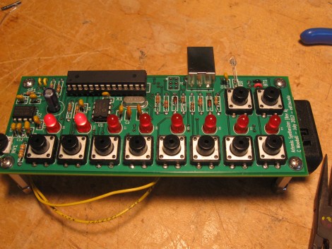
The Artemis Synthesizer was created as a kit for Boston University’s Artemis Project. This project aims to teach female rising high school freshmen about computer science with hands-on activities. [Chris] based the kit on a ATMEGA328P microcontroller and a MCP4921 digital to analog converter. It can be used in a keyboard mode, where the buttons toggle various notes of the scale, or in a sequencer mode, where the buttons are used to toggle pre-programmed sequences.

[Chris] wanted the kit to be usable by the students after the workshop, so he used an optical link dubbed the “Optoloader” to program new sequences and waveforms into the device. A web based application allows for waveforms and sequences to be built in the browser, then programmed by holding a phototransistor up to a blinking square. The square flashes black and white corresponding to a Biphase Mark Code encoded message. This is decoded by the microcontroller on the synthesizer and stored in memory. As a result, no special hardware is needed to play new waveforms and sequences.

[Chris] has a thorough write up for the project, including feedback surveys from the students. He plans to add more specific information about the Optoloader in the future.

Check out a video of the kit in action after the break.

Continue reading “Artemis Synthesizer Kit”

Simple Proximity Sensor

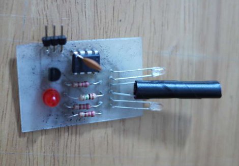
[Dustin Andrews] built this add-on board which works as a proximity sensor. He wanted a standalone sensor for his Arduino projects which would use a single pin as a trigger. This lets him alert the Arduino when an object approaches the sensor without the need for polling or extra code on the Arduino side of things.

As you can see, a single chip on the board takes care of all the work. That’s an ATtiny13, they’re inexpensive and sometimes you can even salvage them from consumer electronics like this color changing light bulb. The microcontroller monitors the phototransistor which is wrapped in electrical tape to isolate it from the IR LED emitters on either side. This setup creates a reflective sensor. When an object nears the board, the infrared light from the emitters reflects off of it and onto the phototransistor. And since the Arduino works as an AVR programmer you don’t need special hardware to program the device.

Glove-based Touch Screen From A CRT Monitor

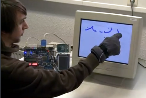
Here’s a bulky old CRT monitor used as a touch-screen without any alterations. It doesn’t use an overlay, but instead detects position using phototransistors in the fingertips of a glove.

Most LCD-based touch screens use some type overlay, like these resistive sensors. But cathode-ray-tube monitors function in a fundamentally different way from LCD screens, using an electron gun and ring of magnets to direct a beam across the screen. The inside of the screen is coated with phosphors which glow when excited by electrons. This project harness that property, using a photo transistor in both the pointer and middle finger of the glove. An FPGA drives the monitor and reads from the sensors. It can extrapolate the position of the phototransistors on the display based on the passing electron beam, and use that as cursor data.

Check out the video after the break to see this in action. It’s fairy accurate, but we’re sure the system can be tightened up a bit from this first prototype. There developers also mention that the system has a bit of trouble with darker shades.

Continue reading “Glove-based Touch Screen From A CRT Monitor”

Dual-monitor Work Stations Aims To Keep You On The Treadmill Longer

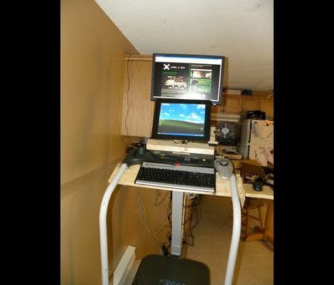
In an effort keep his workout schedule on track [Jamie] built himself this dual-screen treadmill work station. He picked up the treadmill for about $50 on eBay, and after some follies with its shoddy construction, ended up with a pretty nice setup.

The first rendition of this project was just a wooden shelf to hold a laptop. But after the treadmill fell apart, sending his laptop tumbling, he reinforced the machine and added a bunch of stuff in the process. There’s now some custom electronics used to track his progress. He painted a white square on the black belt that makes up the running surface. That is monitored by a PIC microcontroller via a phototransistor and op-amp. He uses a USB data acquisition card to feed the belt-revolution count to the computer for use in tracking his workouts.

The presence of a computer in his setup would make Internet logging a snap too. The exercise bike we looked at on Saturday used a direct Ethernet connection for its logging, but [Jamie’s] setup could be used in the same way. He just needs a script to bridge the collected data with an Internet logging site’s API.

Micromouse Wins 2011 Maze Race In Under 4 Seconds

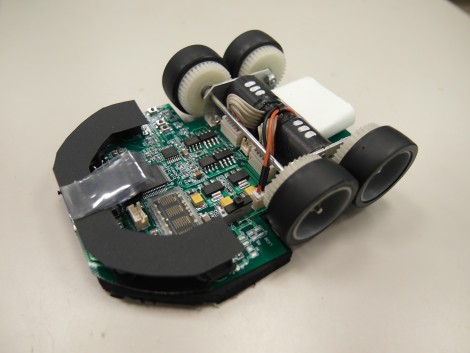
It’s off to the races once again with the Micomouse maze solving contest at the 2011 RoboGames. This is a picture of the winner, a bot called Min7 (main page) which was built by [Ng Beng Kiat]. Using four phototransistors and a flash sensor it managed to first map the contest maze, then speed run it in under four seconds. See both runs in videos after the break. He’s certainly got a leg up on the bots we saw last year. Min7 beats them both in time, and overall control during the speed run.

[Ng] mentions that this year is the first time he’s built a micromouse with four wheels instead of two. There’s a gyro on board which aids navigation by feeding the orientation data to the STM32 chip which controls the device. We took a moment to page through his past designs. It’s remarkable how they’ve evolved through the years. Continue reading “Micromouse Wins 2011 Maze Race In Under 4 Seconds”

Synthesizing Sound With A Light Sensitive Pen And CRT Television

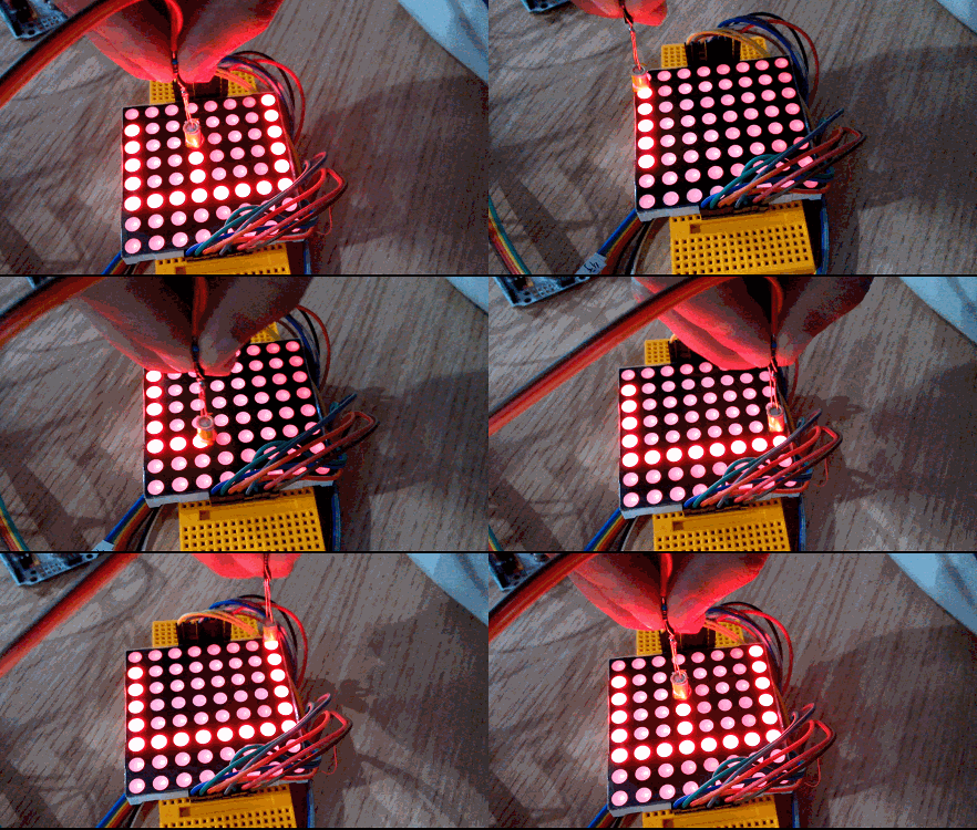
Here’s the latest project from [Niklas Roy’s] workshop. Lumenoise is an audio synthesizer controlled by drawing with a light-sensitive pen on a CRT television.

The pen is a self-contained module which connects to the TV via audio and composite video RCA plugs. Inside the clear pen housing you’ll find a microcontroller which generates the audio and video. The business end of the pen contains a phototransistor which lets the ATmega8 take a reading from the video screen. Since the chip is generating that video signal, it’s possible to calculate the pen tip’s position on the screen and modulate the sound output based on that data. You can watch a recording of the results in the video after the break.

This is a very simple circuit to build, and [Niklas] makes the point that most of us have a CRT hanging around in a dark corner somewhere. We think this would be a fantastic soldering project to do with the kids, and that this would be right at home as a children’s museum piece because of the wow factor involved in playing around with it.

We can really tell from this and some of his past projects that [Niklas] just loves the 8-bit audio.

Continue reading “Synthesizing Sound With A Light Sensitive Pen And CRT Television”

Measuring RPM With Reflective Sensors

[Arao] wanted to measure the RPM of a spinning wheel using parts that he could scavenge from his junk box. A bit of thought led him to build a reflective sensor which can measure the spinning of a wheel (translated).

He got his hands on an infrared phototransistor which had been used as part of the remote control for some consumer electronics. Snooping around with his multimeter helped him establish the pin out of the device. By positioning an IR LED inside of a shroud, yet adjacent to the phototransistor, he can measure the intensity of the LED’s light as it is reflected off of nearby surfaces. The pulley seen above has a piece of electrical tape on it. When this passes by the LED, less of the infrared light is reflected and the drop in intensity is picked up by the phototransistor. [Arao] made the system rock-solid by rolling an LM358 op-amp into the circuit. He’s posted the schematic as well as some screen shots from an oscilloscope during testing.