DIY Low-power PSU For Home Server Use

diy_pc_psu

[Viktor] decided to replace his old power hungry home server with a model that is much easier on the old electric bill. The new motherboard uses an Intel Atom chip and consumes far less power than its predecessor. He figured there was no reason to use a bulky ATX power supply when all he needed was 12V for the mainboard and a pair of 5V rails for his hard drives, so he decided to build a PSU himself.

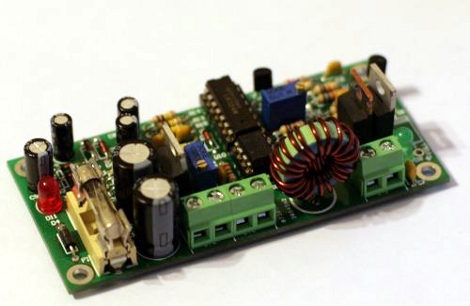
He sourced a 100VA toroid transformer as the basis of the power supply due to its popularity with audio amp builders, adding a standard bridge rectifier and smoothing capacitor before regulating the DC output. A pair of switching regulators were added, one for the 6A, 12V, and a second for the 1.5A, 5V supply. The motherboard only requires about 18W at full tilt, so the PSU should be more than sufficient for his needs.

Schematics and board layouts are available for free on his site, if you are in the market for your own DIY low-power PSU.

Looking for more build to suit electronics?  Check out this DIY amp we featured just the other day.

[Thanks, Chris]

PC Casemod-inspired Benchtop PSU

benchtop_psu

[Will] had a cheap power supply sitting around, and decided to turn it into a full-featured benchtop PSU. Inspired by some of the other benchtop supplies we have featured in the past, he decided that he wanted his PSU to be more than just a simple-looking box sitting on his work bench. Taking some cues from PC case modding, he put together a unit that is not only very useful, but also quite sharp looking.

The frame of the case was crafted from aluminum angle, while all of the other flat surfaces were made using black polycarbonate. He installed the standard 12v, 3.3v, and 5v terminals you would expect from any benchtop PSU, complete with an LCD display showing the voltages provided by each rail as measured by an Arduino stationed inside the case. Additionally, he installed a variable terminal capable of providing 1.3v-30v, along with its own LCD display. The most unique feature is the multimeter embedded in the front of the case, which makes it virtually impossible to lose.

The case is finished off as you might expect, if you have seen any of his previous work. It features LED lighting on the inside, large fans on either side of the case for optimal air flow, and a pair of machined aluminum handles.

Be sure to check out the quick video below of the PSU being powered on.

Continue reading “PC Casemod-inspired Benchtop PSU”

ATX Psu Turned Into An Adjustable Voltage Bench Supply

Here’s a fancy way to convert an ATX powers supply into a bench supply. [TG] didn’t just cut off the motherboard connector and add banana plugs, but improved the functionality. Right off the bat you’ll notice that he’s added a control panel. There is an Ammeter and Ohmmeter to let you know what the unit is putting out. He added an MIC29152WT adjustable voltage regulator so that he’s not limited to the fixed voltages of the psu. As a final touch he added an external voltage probe which can be used with the flick of a switch. It’s no replacement for a proper bench supply, especially since it doesn’t have adjustable current limiting, but it’s a nice improvement upon previous psu hacks.

Beginner Concepts: Powering Your Projects

Powering your gadgets generally seems like a necessary evil. To help with this [Felipe La Rotta] made a really nice bench power supply using a PC power supply and a LM317 adjustable voltage regulator. PC power supplies are an example of a switched power supply(more on that later).  The LM317 is a type of linear voltage regulator that allows for adjusting the output voltage by varying some resistors. Whats the best way to power your circuits? well that depends…

Continue reading “Beginner Concepts: Powering Your Projects”

Bench Supply With Current Limiting

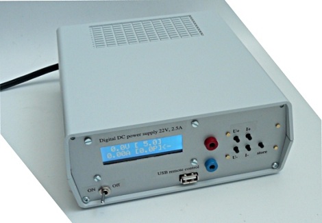
This is a bench power supply with adjustable voltage and current limiting. [Sylvain’s] creation can regulate 0-25 volts while sourcing 0-5 amps. Current limiting is a nice feature as it will allow you to test your prototypes to ensure the power regulator you choose will not be over or underpowered.

This supply is really a two-in-one. The case has two separate circuits so that you can have different power rails going at the same time. There is a microcontroller involved, but the ATmega32 doesn’t do anything more than measure the voltage and amperage and drive the graphic LCD screen. Two potentiometers are responsible for setting the voltage and limiting the current.

[Thanks Sargonout]

PIC Programmable Power Supply

This programmable power supply is the perfect addition to your bench tools. [Debraj Deb], who previously built a whole house power monitor, designed this build around a PIC 18F4520 microcontroller. The desired voltage is set with an attached keypad, resulting in a digital output on the 8-bits of port D. The port connects to another protoboard with an R-2R digital-to-analog converter resulting in the target voltage. A set of transistors amplifies the current and a power transistor then takes care of the final output. After the break you’ll find two videos, the first walks us through the hardware and the second demonstrates the device in action, along with measurements of its performance. This certainly provides a lot more functionality than an ATX power-supply conversion.

Update: A big thanks to [Debraj] who sent us a code package as well as the schematic (PDF) used during testing. We’re having trouble getting the code package up for download right now. Check back later, hopefully we’ll have it up soon.

Continue reading “PIC Programmable Power Supply”

EL Wire: Make It, Connect It, Power It

[Jeri’s] back with a series of videos that outlines the step-by-step electroluminescent wire manufacturing, making EL panels from PCBs, and assembling power supplies for EL hardware. These concepts are actually quite approachable, something we don’t expect from someone who makes their own integrated circuits at home.

The concept here is that an alternating current traveling through phosphors will excite them and produce light. You need two conductors separated by a dielectric to get the job done. For wire, [Jeri] uses one strand of enameled magnet wire and one strand of bare wire. The enamel insulates them, protecting against a short circuit.

But that’s not all, she also tests using a circuit board as an EL panel. By repurposing the ground plane as one of the conductors, and using the solder mask as the dielectric she is able to paint on a phosphor product resulting in the glowing panel.

Finally, you’ve got to get juice to the circuit and that’s where her power supply video comes into the picture. We’ve embedded all three after the break. It’s possible that this is cooler than blinking LEDs and it’s fairly inexpensive to get started. The circuitry is forgiving, as long as you don’t zap yourself with that alternating current.

Continue reading “EL Wire: Make It, Connect It, Power It”