Blinky Headgear

This hat has a chasing LED feature thanks to our old friend the 555 timer. [BananaSlug] even built in the option to change the speed at the push of a button.

His design starts out with a costume hat. Each of the 25 LEDs is soldered to a 2×4 hole chunk of protoboard. The LED package is pushed through a slit in the hat, but the protoboard remains on the inside where it can be sewn in place. From there [BananaSlug] soldered one negative bus around the circumference, and an individual positive lead from each module back to the control board. They’re addressed by a set of CD4017 decade counters which are clocked by the 555 timer circuit.

This is a great little analog/logic project and the style is perfect if you’ve got the coat to go along with it.

[David] Hand Soldered A Blinky Ball… And You Can Too!

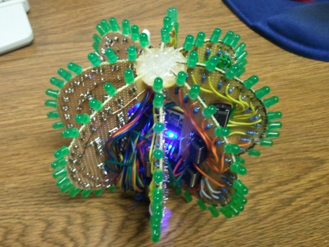
This is a blinky ball that [David] designed, built, and programmed himself. Does it look familiar? It should, he took his inspiration from the original prototype, and the Hackerspace-produced derivative. [David’s] version is not as small, or as blinky, but in our minds the development process is the real reason for building something like this. He took a great idea and figured out how he could pull it off while pushing his skill set, staying within his time and budget constraints.

The project is powered by an Arduino nano which resides in the core of the ball. [David] used protoboard sourced locally for each of the slices, soldering green LEDs along the curved edges, and added shift registers to drive them. The ball is driven by a LiPo battery which can power it for about 45 minutes. You can see the animation designs he coded in the clip after the break.

Continue reading “[David] Hand Soldered A Blinky Ball… And You Can Too!”

[Scot] Whips Up Breakout Board For His ARM Breakout Board

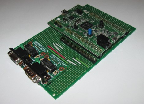
[Scot Kornak] got his hands on the new STM32 Discovery Board. He got his as a free giveaway, but at only $18 he probably would have picked one up anyway. His one complaint about the device is that he dual pin-headers which break out the ARM processor’s pins are not the most convenient for hooking up external components. He decided to make his own breakout board which would give him a more robust solution for the components he uses all the time.

The protoboard that he chose as a base is quite interesting. It’s made for interfacing DIL pin headers just like the ones on the STM32F4 Discovery board. Each row of the dual header is carried down the board perpendicular to those headers. [Scot] cut the traces underneath the STM32 board to isolate the right and left sides. He then added RS232 hardware to one side, while including another pair of DIL headers to break out the rest of the unused pins.

This is all he’s got so far, but there’s plenty of room on the base board to add more as the need arises.

Hackaday Links: December 16, 2011

Free-form Christmas ornament

Here’s [Rob]’s free form circuit that’s a Christmas ornament for geeks. It looks great, but sadly isn’t powered through a Christmas light strand. It’s just as cool as the skeletal Arduino we saw.

Prototyping with flowers

Well this is interesting: protoboard that’s specifically made to make SMD soldering easier. The guys at elecfreaks went through a lot of design iterations to make sure it works.

We’ll call it Buzz Beer

The days are getting longer and cabin fever will soon set in. Why not brew beer in your coffee maker? It’s an oldie but a goodie.

Christmas oscilloscope

With just an ATtiny and a little bit of  futzing around changing the coefficients of a partial differential equation, you too can have your very own oscilloscope Christmas tree. Don’t worry though, there are instructions on how to implement it with an Arduino as well. HaD’s own [Kevin] might be the one to beat, though.

So what exactly does a grip do?

You know what your home movies need? A camera crane, of course. You’ll be able to get some neat panning action going on, and maybe some shots you couldn’t do otherwise. Want a demo? Ok, here’s a guy on a unicycle.

Kequencer 2.0 Is Cheaper And Easier To Build — Still Awesome

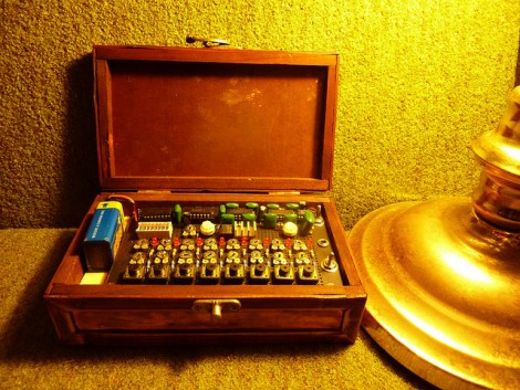
[Rich Decibels] decibels received so much interest in his original sequencer build that he decided to make another one that was a bit easier and less expensive to replicate. The original design, called the Kequencer, featured a nicely finished look for the user interface. For the Keyquencer 2.0 he decided that adding a lid to the enclosure meant not spending quite as much for controls (nice looking knobs tend to increase the cost of potentiometers).

A rectangle of protoboard serves as the panel face for the device. It looks like he painted it black on top so that it doesn’t distract from the neatly organized parts layout. He used point-to-point wiring to make most of the hookups, but he did create a board layout which will help to guide you when the number of wires starts to get out of hand. This was made after the fact and he regrets not having it for the initial build. Check out the demonstration video embedded after the break to hear how the second iteration sounds.

Continue reading “Kequencer 2.0 Is Cheaper And Easier To Build — Still Awesome”

Printed Circuit Board Minus The Printed Traces

Reader [Osgeld] is a board-layout ninja. He populated this 4×4 LED matrix board without having a layout plan to start with. Watch it develop in slideshow format to see the art work he performs. The display is driven by a shift-register and he’s included all the proper parts like resistors and transistors, yet he makes everything fit. Why is this amazing? He’s using uninsulated wire and not a single one of them crosses another wire. He’s physically designing a printed circuit board, routing the traces as he solders away. He’s built this to use with an Arduino shift register tutorial and our only question is where is the header to hook this board to a microcontroller?

Center Speaker Amp For An IPod

center_speaker_ipod_amp

A few weeks ago we saw [Jaroslaw’s] universal credit card spoofer. Now he’s sent in a project that incorporates an amplifier into a center speaker for use with an iPod or any device with an audio jack.

The build has two main components; an LM4950 audio amplifier and a center channel speaker he picked up for $3 at Goodwill. The circuit used is straight from the datasheet and he’s provided the four necessary resistor values for you in his writeup. An old set of headphones was butchered for the audio connector and DC power can be provided by any 6-12V source.

The final circuit was built on some protoboard. The speaker housing has plenty of room to fit everything in for a nice finished look. Pretty simple, and except for the IC, this should be an easy salvage project for most folks.