Homebrew NSA Bugs

NSA

Thanks to [Edward Snowden] we have a huge, publicly available catalog of the very, very interesting electronic eavesdropping tools the NSA uses. Everything from incredibly complex ARM/FPGA/Flash modules smaller than a penny to machines that can install backdoors in Windows systems from a distance of eight miles are available to the nation’s spooks, and now, the sufficiently equipped electronic hobbyist can build their own.

[GBPPR2] has been going through the NSA’s ANT catalog in recent months, building some of the simpler radio-based bugs. The bug linked to above goes by the codename LOUDAUTO, and it’s a relatively simple (and cheap) radar retro-reflector that allows anyone with the hardware to illuminate a simple circuit to get audio back.

Also on [GBPPR2]’s build list is RAGEMASTER, a device that fits inside a VGA cable and allows a single VGA color channel to be viewed remotely.

The basic principle behind both of these bugs is retroreflection, described by the NSA as a PHOTOANGLO device. The basic principle behind these devices is a FET in the bug, with an antenna connected to the drain. The PHOTOANGLO illuminates this antenna and the PWM signal sent to the gate of the FET modulates the returned signal. A bit of software defined radio on the receiving end, and you have your very own personal security administration.

It’s all very cool stuff, but there are some entries in the NSA catalog that don’t deal with radio at all. One device, IRATEMONK, installs a backdoor in hard drive controller chips. Interestingly, Hackaday favorite and current Hackaday Prize judge [Sprite_TM] did something extremely similar, only without, you know, being really sketchy about it.

While we don’t like the idea of anyone actually using these devices, the NSA ANT catalog is still fertile ground for project ideas.

Continue reading “Homebrew NSA Bugs”

A SI5351 clock generator chip and an Arduino

Generate Clocks With The SI5351 And An Arduino

If you’re dealing with RF, you’ll probably have the need to generate a variety of clock signals. Fortunately, [Jason] has applied his knowledge to build a SI5351 library for the Arduino and a breakout board for the chip.

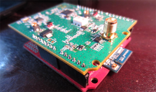
The SI5351 is a programmable clock generator. It can output up to eight unique frequencies at 8 kHz to 133 MHz. This makes it a handy tool for building up RF projects. [Jason]’s breakout board provides 3 isolated clock outputs on SMA connectors. A header connects to an Arduino, which provides power and control over I2C.

If you’re looking for an application, [Jason]’s prototype single-sideband radio shows the chip in action. This radio uses two of the SI5351 clocks: one for the VFO and one for the BFO. This reduces the part count, and could make this design quite cheap.

The Arduino library is available on Github, and you can order a SI5351 breakout board from OSHPark.

RasPi FM Transmitter

Easily Turn Your Raspberry Pi Into An FM Transmitter

Have you ever wanted to be your own radio DJ? [Kevin] has made it easier than ever with his Raspberry Pi FM Transmitter program. The program is written in C. [Kevin] has made source code is available along with a compiled binary.

PIFM allows you to load up any audio file and specify a frequency to transmit. The program will then use PWM to modulate the audio sample through the Pi’s GPIO4 pin. [Kevin] claims that the RasPi alone will only transmit around a 10 cm distance. He says that making a simple antenna out of a jumper wire can increase the distance to around 100 meters. All you have to do is hook up the wire to the GPIO4 pin to drastically increase the range.

The legality of such a transmitter will vary from place to place, so be sure to check out your local regulations before you go transmitting audio on regulated frequencies. If this kind of thing is interesting to you, you may want to investigate ham radio. It’s not all Morse code and old fogies. Some people claim it’s a hacker’s paradise.

[via Reddit]

Controlling RC Toys With The Raspi

signal

An interesting trick you can do with a a fast CPU and a GPIO pin mapped directly to memory is an FM transmitter. Just toggle a pin on and off fast enough, and you have a crude and kludgy transmitter. [Brandon] saw a few builds that turned a Raspberry Pi into an FM radio transmitter and realized a lot of toy remote control cars use a frequency in the same range a Pi can transmit at. It’s not much of a leap to realize the Pi can control these remote control cars using only a length of wire attached to a GPIO pin.

The original hack that turned a Pi GPIO pin into an FM transmitter mapped a GPIO pin to memory, cycled through that memory at about 100 MHz, and added a fractional divider to slightly adjust the frequency, turning it into an FM transmitter. Cheap RC cars usually listen for radio signals at 27 and 49 MHz. It doesn’t take much to realize commanding RC cars with a Pi is possible.

The only problem with this idea is that most RC cars use pulse modulation. For an RC transmitter to send the command for ‘forward’, a synchronization pulse is sent, then a series of pulses and pauses. The frequency doesn’t change at all, something the originally FM code doesn’t do. [Brandon] realized that if he just moved the frequency up to something the RC car wasn’t listening to, that would register as a zero.

All that was left was to figure out the command codes for his RC truck. For this, [Brandon] decided brute force would be the best option. Armed with a script and a webcam, he cycled through all possible combinations until the webcam detected a moving truck. Subtlety brilliant, if you ask us. Of course more complex commands required an oscilloscope, but now [Brandon] has a git full of all the code to control a cheap RC car with a Pi.

Build Your Own Radio Clock Transmitter

Deep in the Colorado foothills, there are two radio transmitters that control the time on millions of clocks all across North America. It’s WWVB, the NIST time signal radio station that sends the time from several atomic clocks over the airwaves to radio controlled clocks across the continent. You might think replicating a 70 kW, multi-million dollar radio transmitter to set your own clock might be out of reach, but with a single ATtiny45, just about everything is possible.

Even though WWVB has enough power to set clocks in LA, New York, and the far reaches of Canada, even a pitifully underpowered transmitter – such as a microcontroller with a long wire attached to a pin PWMing at 60kHz – will be more than enough to overpower the official signal and set a custom time on a WWVB-controlled clock. This signal must be modulated, of course, and the most common radio controlled clocks use an extremely simple amplitude modulation that can be easily replicated by changing the duty cycle of the carrier. After that, it’s a simple matter of encoding the time signal.

The end result of this build is an extremely small one-chip device that can change the time of any remote-controlled clock. We can guess this would be useful if your radio controlled clock isn’t receiving a signal for some reason, but the fact that April 1st is just a few days away gives us a much, much better idea.

TDOA (Time Difference Of Arrival) Directional Antenna

tdoa-antenna-tutorial

We have posted articles in the past on directional antennas such as Yagi antennas used for transmitter hunting otherwise known as fox hunting. Those types of antennas and reception suffer from one major drawback, which is as you get close to the transmitter the S meter will go full scale. At which time the transmitted signal appears to be coming from all directions. To correct for this problem you need to use clever signal attenuators or change to a poor receiving antenna as well as tuning off frequency effectively making your receiver hard of hearing so that only the direct path to the transmitter is loudest.

There is another popular type of antenna that you can build yourself called a TDOA which stands for Time Difference of Arrival. [Byon Garrabrant N6BG]  shared a short video tutorial on the functionality of his home built TDOA antenna. Effectively this is an active antenna that uses a 555 chip or, in [Byon’s] case, a PIC chip to quickly shift between two receiving dipole antennas at either end of a shortened yardstick. In his explanation you learn that as the antenna ends move closer or farther from the source a 640 Hz generated audio tone will go from loud to very soft as the antennas become equal distance from the source. This type of directional reception is not affected by signal strength. This means you can be very close to a powerful transmitter and it will still function as a good directional antenna.

The current circuit diagram, BOM and source code are all available on [Byon’s] TDOA page.

The reason [Byon] used a programmable PIC instead of the 555 for his design is because he wants to add a few more modifications such as feeding back the audio output to the PIC in order to programmatically turn on a left or right LED indicating the direction of the transmitter. Furthermore, he plans on adding a third antenna in a triangular configuration to programmatically control a circle of 6 LEDs indicating the exact direction of the signal. When he finishes the final modifications he can drive around with the antenna array on his vehicle and the circle of LEDs inside indicating the exact direction to navigate.

We look forward to seeing the rest of the development which might even become a kit someday. You can watch [Byon’s] TDOA video after the break.

Continue reading “TDOA (Time Difference Of Arrival) Directional Antenna”

Verifying A Wireless Protocol With RTLSDR

rtlsdr_nrf905_rtlizer

[Texane] is developing a system to monitor his garage door from his apartment. Being seven floors apart, running wires between the door and apartment wasn’t an option, so he turned to a wireless solution. Testing this wireless hardware in an apartment is no problem, but testing it in situ is a little more difficult. For that, he turned to software defined radio with an RTLSDR dongle.

The hardware for this project is based around a TI Stellaris board and a PTR8000 radio module. All the code for this project was written from scratch (Github here), making it questionable if the code worked on the first try. To test his code, [Texane] picked up one of those USB TV tuner dongles based around the RTL2832U chipset. This allowed him to monitor the frequencies around 433MHz for the packets his hardware should be sending.

After that, the only thing left to do was to write a frame decoder for his radio module. Luckily, the datasheet for the module made this task easy.

[Texane] has a frame decoder for the NRF905 radio module available in his Git. It’s not quite ready for serious applications, but for testing a simple radio link it’s more than enough.