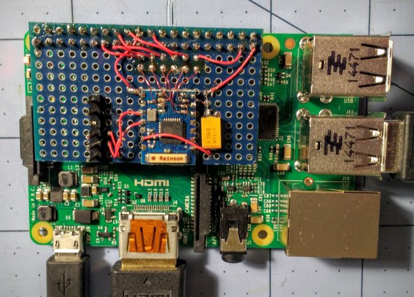
There’s no better way to learn how to program a computer than assembly, and there’s no better way to do assembly than with a bunch of blinkenlights and switches. Therefore, the best way to learn programming is with a PDP-11. It’s a shame these machines are locked up in museums and the garages of very cool people, but you can build your own PDP-11 with a Raspberry Pi and just a few extra components.
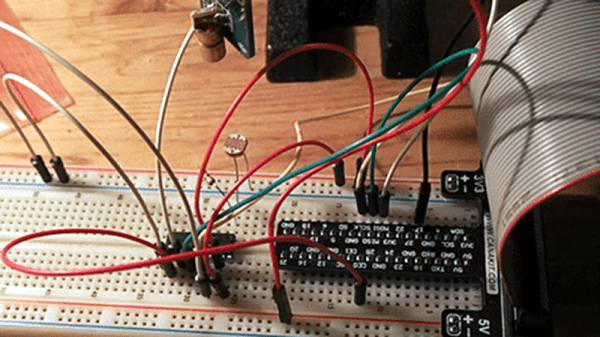
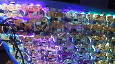
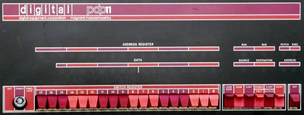
[jonatron] built his own simulated version of the PDP-11 with a lot of LEDs, a ton of switches, and a few 16-bit serial to parallel ICs. Of course the coolest part of any blinkenlight simulator are the front panel graphics, and here [jonatron] didn’t skimp. He put those switches and LEDs on a piece of laser cut acrylic with a handsome PDP11 decal. The software comes with a load of compiler warnings and doesn’t run anything except for very simple machine code programs. That’s really all you can do with a bunch of toggle switches and lights, though.
If this project looks familiar, your memory does not deceive you. The PiDP-8/I was an entry in this year’s Hackaday Prize and ended up being one of the top projects in the Best Product category. We ran into [Oscar], the creator of the PiDP-8, a few times this year. The most recent was at the Hackaday SuperConferece where he gave a talk. He’s currently working on a replica of the king of PDPs, the PDP-11/70.
Video below.