When the ever-versatile Raspberry Pi was released, the potential for cheap video game emulation was immediately obvious. Some of the very first Raspi projects to hit the internet were arcade cabinets, and it wasn’t long until people were making them portable. A purpose-build Linux distort called RetroPie has become very popular specifically because of the Raspi’s game-emulation potential. However, the actual hardware for these emulation systems isn’t always the most aesthetically (or ergonomically) pleasing. That’s where reddit user [Cristov9000] has managed to stand out from the crowd.
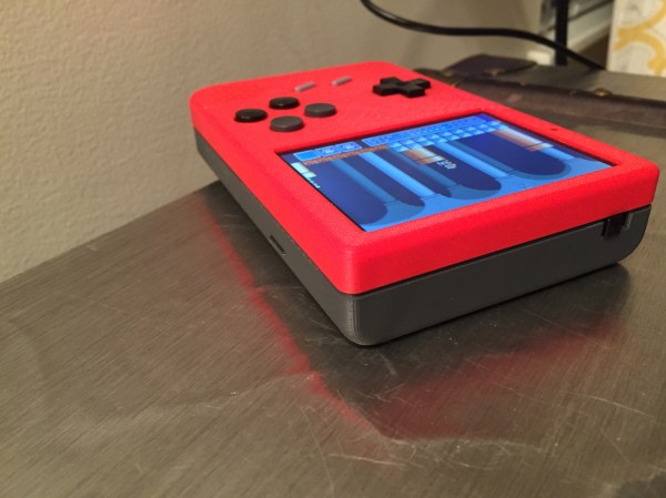
[Cristov9000] accomplished this by combining high-quality design (and 3D printing) with the careful use of original Nintendo parts. Game Boy and SNES buttons and elastomers were used to achieve the correct button feel. Other original Game Boy parts, like the volume wheel and power switch, ensure that the system feels as much like 1989 OEM hardware as possible.
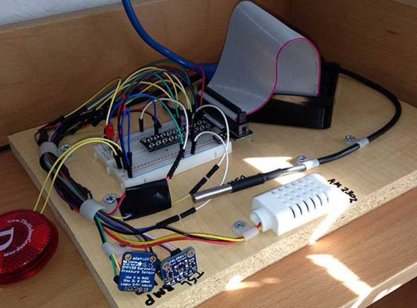
Also impressive is the internal hardware, including 3 custom PCBs used to tie everything together to work via the Raspberry Pi 2 GPIO pins. The display is a 3.5″ TFT screen, and with the 6000 mAh it can handle gameplay for more than 7 hours. Other details, like the integrated mono speaker and rear shoulder buttons complete the experience. Combined with the RetroPie and an assortment of emulators, this is one of the most impressive portable gaming builds we’ve seen, especially among a crowded list of awesome raspi-based Game Boy builds.
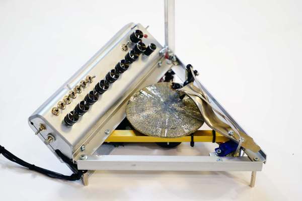
 Pyrite discs, also known as pyrite suns or pyrite dollars, are a form of pyrite in which the crystallization structure forms a disc with radial striations. Pyrite discs are unique to the area around Sparta, Illinois, and are generally found in coal mines there. They have no real practical use, but are a favorite of mineral collectors because of their interesting aesthetics.