Custom Cut Pinwheel Makes A Useful HVAC Duct Flow Meter

Everyone is familiar with pinwheels, and few of us haven’t crafted one from a square of paper, a stick, and a pin. Pinwheels are pretty optimized from a design standpoint, and are so cheap and easy to build that putting a pinwheel to work as an HVAC duct flow meter seems like a great idea.

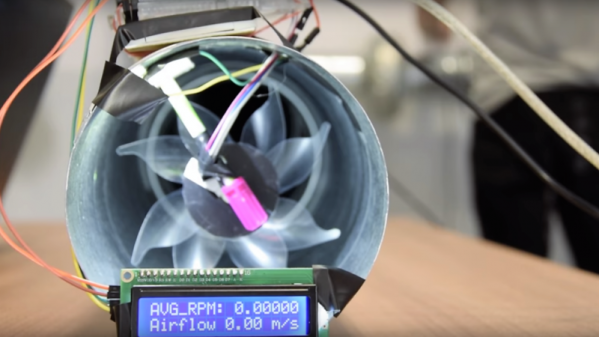
Great in theory, perhaps, but as [ItMightBeWorse] found out, a homemade pinwheel is far from an ideal anemometer. His experiments in air duct flow measurements, which previously delved into ultrasonic flow measurement, led him to try mechanical means. That calls for some kind of turbine producing a signal proportional to air flow, but a first attempt at using a computer fan with brushless DC motor failed when a gentle airflow couldn’t overcome the drag introduced by the rotor magnets. But a simple pinwheel, custom cut from patterns scaled down from a toy, proved to be just the thing. A reflective optosensor counts revolutions as the turbine spins in an HVAC duct, and with a little calibration the rig produces good results. The limitations are obvious: duct turbulence, flimsy construction, and poor bearings. But for a quick and dirty measurement, it’s not bad.

Looking for an outdoor anemometer rather than an HVAC flow meter? We’ve got one made from an old electric motor, or a crazy-accurate ultrasonic unit.

Continue reading “Custom Cut Pinwheel Makes A Useful HVAC Duct Flow Meter”

Line Follower Has Lots Of Recycled Parts, But Zero Brains

Line Followers are a tried-and-true type of robot; both hardware and software need to be doing their job in harmony in order to be successful at a clearly defined physical task. But robots don’t always have microcontrollers and software, as [Mati_DIY]’s zero programming analog line follower demonstrates.

For readers used to seeing a Raspberry Pi or Arduino in almost everything, an analog robot whose “programming” exists only as a harmony between its discrete parts can be an eye-opener as well as an accessible project. A video of the robot in action is embedded below.

[Mati_DIY]’s design uses two CNY70 reflective sensors (which are essentially infrared emitter/phototransistor pairs) and an LM358 dual op-amp. Together, the sensors act as two near-sighted eyes. By using the output of each sensor to drive a motor via a transistor, the presence or absence of the black line is directly and immediately reflected by the motion of the attached motor. The more black the sensor sees, the more the motor turns. Electrically, that’s all that happens; but by attaching the right sensor to the left motor and the left sensor to the right motor, you get a robot that always tries to keep the black line centered under the sensors. Playing with the spacing of the motors and sensors further tweaks the performance.

Continue reading “Line Follower Has Lots Of Recycled Parts, But Zero Brains”

Miniscule Line-Follower

miniscule-line-follower

Building line following robots is fun and easy. Building a line-follower that is this tiny is a different story. The surprising thing for us is that despite how it looks, this robot whose name is Rizeh doesn’t use wheels to get around. [Naghi Sotoudeh] built the line-follower using two vibrating motors, with needles (not shown above) making three points of contact with the ground.

His website is a little sparse, but hit the downloads page to get a PDF file that serves as the build log. We also downloaded the 32 second demo video which is worth it. The magic-marker track that the bot is circumnavigating isn’t any bigger than the palm of your hand!

Onboard the diy PCB you’ll find two GP2S04 IR reflectance sensors which detect the black line on a white paper. The power-up sequence spends a few seconds calibrating these sensors. Speaking of power, [Naghi] went with a lithium polymer cell from a Bluetooth headset. At the heart of it all is an ATtiny45 which uses its hardware PWM capabilities to drive the two motors.

Of course line-followers rank up there with self-balancers as our favorite robot projects. But by far the ones we love the most are the speed-run maze solvers.

Simple Proximity Sensor

[Dustin Andrews] built this add-on board which works as a proximity sensor. He wanted a standalone sensor for his Arduino projects which would use a single pin as a trigger. This lets him alert the Arduino when an object approaches the sensor without the need for polling or extra code on the Arduino side of things.

As you can see, a single chip on the board takes care of all the work. That’s an ATtiny13, they’re inexpensive and sometimes you can even salvage them from consumer electronics like this color changing light bulb. The microcontroller monitors the phototransistor which is wrapped in electrical tape to isolate it from the IR LED emitters on either side. This setup creates a reflective sensor. When an object nears the board, the infrared light from the emitters reflects off of it and onto the phototransistor. And since the Arduino works as an AVR programmer you don’t need special hardware to program the device.

Easy Rotary Encoding For Your Projects

Want to monitor how much a wheel has turned in your project? Then you need a rotary encoder! Here’s a way to add rotary encoding without changing the mounting method of your wheels (translated). [Jorge] added it as a way to improve the functionality of this line-following robot. It uses a paper encoder wheel which is monitored by an optical sensor.

The paper wheel consists of alternating white and black pie pieces. You can make this with a felt-tipped marker, or use a tool like the one we featured a couple of years ago to print out a disc rendered to your own specifications. This is glued to the inside of the wheel and monitored by a CNY70 reflective sensor (the same one used in that electric keyboard retrofit).

The homemade board which holds the sensor can be seen mounted on top of each wheel’s motor. It requires three wires, voltage, ground, and data. The data line is connected to the output of the phototransistor in the CNY70 package so it can be used with a microcontroller interrupt for easy integration with the firmware driving the robot.

[Jorge] goes into some detail about how the added data helps to improve the speed performance seen in the clip after the break.

Continue reading “Easy Rotary Encoding For Your Projects”

POV Bauble Uses DIY Accelerometer To Sync The Image

So we saw this tip come in and thought–oh, another POV device. We watched the video (embedded after the break), took a sip of coffee, then almost sprayed the beverage all over the computer when we realized that this uses a diy sensor to synchronize the POV image.

[Ch00f] came up with the idea for the sensor after seeing a similar implementation on a commercial POV toy. Instead of using a proper accelerometer to sense the motion, the toy uses a plastic bead in a channel. When you move the body of the toy the bead rolls to one end or the other, covering or exposing a reflective sensor.

A similar sensor is used here. A drinking straw servers as the channel, with a paper-covered nylon screw as the bead. [Ch00f] cut a window in the bottom of the straw for his reflective sensor, then sealed each end with a wad of paper.

This method works, but not as well as he had hoped. It seems the refresh rate and timing of the particular sensor he’s using is rather poor. If it were replaced with one that is simply and IR LED and phototransistor (like the sensors from [Jack’s] last video) he thinks it would work a lot better.

via Buildlounge.

Continue reading “POV Bauble Uses DIY Accelerometer To Sync The Image”

UPDATE: Playing Piano With Optical Sensors

[Sebastian Steppeler] has been hard at work on his optical sensors for an electric piano. When we looked in on the project back in October he was testing reflective sensors to increase responsiveness and MIDI data resolution for his electric keyboard. Since then he’s finalized the sensor circuits and produced enough boards to monitor all 88 keys on this full keyboard. You can see the string of PCBs just above the ivories, waiting to be installed. Not only are then in, but he also added sensors for the pedals.

Because the boards were installed by hand, there are some variances in the physical placement. This can have a rather dramatic effect on the readings from the reflective sensors so he has been working out a method of balancing the calibration. Part of this is already being taken care of by the C# interface that he wrote for a PC. Take a few minutes to check out all of his blog posts, then jump down after the break and hear how great it sounds.

Continue reading “UPDATE: Playing Piano With Optical Sensors”