Internal Heating Element Makes These PCBs Self-Soldering

Surface mount components have been a game changer for the electronics hobbyist, but doing reflow soldering right requires some way to evenly heat the board. You might need to buy a commercial reflow oven — you can cobble one together from an old toaster oven, after all — but you still need something, because it’s not like a PCB is going to solder itself. Right?

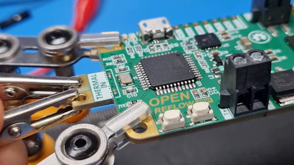
Wrong. At least if you’re [Carl Bugeja], who came up with a clever way to make his PCBs self-soldering. The idea is to use one of the internal layers on a four-layer PCB, which would normally be devoted to a ground plane, as a built-in heating element. Rather than a broad, continuous layer of copper, [Carl] made a long, twisting trace covering the entire area of the PCB. Routing the trace around vias was a bit tricky, but in the end he managed a single trace with a resistance of about 3 ohms.

When connected to a bench power supply, the PCB actually heats up quickly and pretty evenly judging by the IR camera. The quality of the soldering seems very similar to what you’d see from a reflow oven. After soldering, the now-useless heating element is converted into a ground plane for the circuit by breaking off the terminals and soldering on a couple of zero ohm resistors to short the coil to ground.

The whole thing is pretty clever, but there’s more to the story. The circuit [Carl] chose for his first self-soldering board is actually a reflow controller. So once the first board was manually reflowed with a bench supply, it was used to control the reflow process for the rest of the boards in the batch, or any board with a built-in heating element. We expect there will be some limitations on the size of the self-soldering board, though.

We really like this idea, and we’re looking forward to seeing more from [Carl] on this.

Continue reading “Internal Heating Element Makes These PCBs Self-Soldering”
PCB Hotplate Has Integrated Heating Element Traces

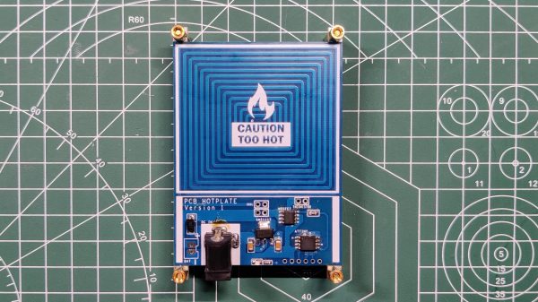
Normally when we talk about PCBs and hotplates, we’re talking about reflowing solder. In this build from [Arnov Sharma], though, the PCB itself is the hotplate!

The idea was to create a compact hotplate for easily reflowing small PCBs. To achieve that, [Arnov] designed a board with a thick coil trace that acts as a heating element. The full coil trace has a resistance of 1.9 ohms, and passing electricity through it generates plenty of heat. Running off a 12 volt supply, the mini hotplate is capable of reaching a maximum temperature of 214°C. Higher voltages can push that figure higher.

The board is intended to self-regulate, with an ATtiny13 onboard and a thermistor to measure temperature. However, in the initial design, this feature didn’t quite work properly. Version 2 is intended to include a better temperature sensor and a OLED screen for displaying the current temperature to the user.

We’ve seen other tiny hotplate builds before, too. They’re great for smaller projects and for hacking on the go! Video after the break.

Continue reading “PCB Hotplate Has Integrated Heating Element Traces”

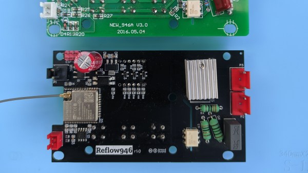
New controller PCB shown below the original one. The new PCB has an ESP module with an antenna, a lot of support circuitry, and all the same connectors that the original board does.

Controller For 946C Hotplate Adds Reflow Profile Upload Over BLE

Reflow hotplates are a wonderful tool for PCB assembly if you can keep your designs single-sided. The 946C hotplate in particular has been on hackers’ radar for a while – a 200x200mm working surface hotplate available for under $100 is a decent investment. As with other reflow tools, it was a matter of time until someone made a replacement controller for it. This one, you’ll want to keep in mind – it’s a replacement controller project by [Arnaud Durand] and [Elias Rodriguez Martin], called Reflow946.

Keeping to best practices, the board is a drop-in replacement for the stock controller – swap cables over and go. The host processor is an ESP32, and it lets you can program reflow profiles in using BLE, with a Python application to help. The whole design is open-source and on GitHub, of course – keeping with best 3D printing traditions, you can already order the parts and PCBs, and then assemble them using the hotplate you’re about to upgrade. As far as aftermarket controllers go, here’s no doubt this board gives you way more control in reflow and lets you compensate for any possible subpar calibration while at it. Continue reading “Controller For 946C Hotplate Adds Reflow Profile Upload Over BLE”

Versatile Reflow Oven Controller Uses ESP32-S2

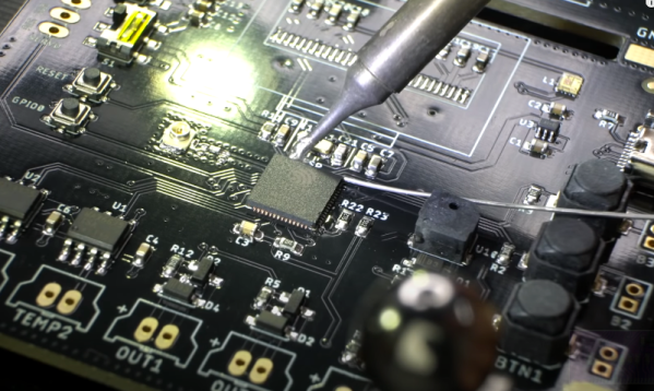
[Maker.Moekoe] wanted a single controller board that was usable with different reflow ovens or hotplates. The result is a versatile board based on the ESP32-S2. You can see a video of the board’s assembly in the video below.

The board sports several inputs and outputs including:

  • 2x MAX6675 thermocouple sensor input
  • 2x Fan output with flyback diodes
  • 2x Solid state relay output
  • 3x Buttons
  • 1x LED
  • 1x Buzzer
  • 1x Servo motor output
  • 0.96 inch OLED display

You could probably find a use for the board for other similar applications, not just ovens.

The video is oddly relaxing, watching parts reflow. It is like watching a 3D printer, no matter how many times we see it, we still find it soothing to watch. You can also see how he integrated the board with a toaster oven.

Overall, the board looks great and the workmanship is also very good. If you’ve never seen anyone set heat-set threaded inserts into a 3D printed piece, be sure to watch around the four minute mark.

We’ve seen plenty of oven projects. You can even use an Easy Bake oven.

Continue reading “Versatile Reflow Oven Controller Uses ESP32-S2”

Reflow Hotplate Teardown Uncovers The Bare Minimum

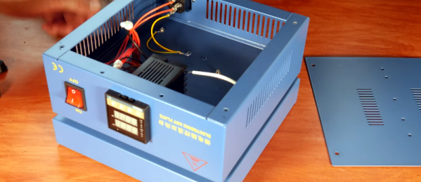
[EEforEveryone] is trying to find a good hot plate for reflow soldering. After trying one cheap unit, he got another one. He was a bit underwhelmed. The grounding was suspect and the bed wasn’t totally flat. He tore it apart and was surprised that there was very little inside. While the construction wasn’t perfect, it was better than the previous unit. You can see a video of the teardown and review below.

Before powering it up, the first order of business was to rewire the ground system. After that, it was time to try it. However, by confusing Fahrenheit and Centigrade, he set the temperature much higher than necessary which creating a little smoke. Fixing the temperature helped, but there was still a bit of a smoky smell that eventually subsided.

The verdict? The hot plate worked well enough, but you probably do want to check the ground wiring before using it. That’s often a good idea where cheap equipment is concerned, anyway. But the real takeaway is that it looks like you could homebrew something equivalent without much trouble. The controller is an off-the-shelf module. A switch and a plug aren’t hard to figure out. The heating element could be a silicone heater or PCB heater meant for a 3D printer.

Of course, there are other options. You could use a wok. Or why not a waffle iron? You can also make a custom PCB.

Continue reading “Reflow Hotplate Teardown Uncovers The Bare Minimum”

Mystery Effect Causing LEDs To Glow During Reflow

Sometimes you notice something small that nevertheless you can’t explain. [Greg Davill] found himself in just such a situation this week when he noticed some green LEDs glowing dimly when reflowing some boards. Naturally, [Greg] set out to investigate.

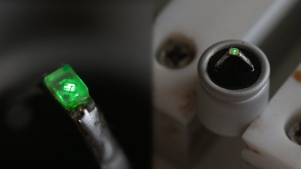
The green LEDs were wired up as power indicators, and [Greg] suspected that the polymer caps on the board might be generating a small current somehow that was causing the LEDs to light up ever so slightly. A simple test hooked a polymer cap directly up to a multimeter. When warmed with a heat gun, the meter showed a small current “in the 5-10 uA range.”

Going further, [Greg] soldered an LED to the cap and once again heated it up, this time to 100° C. The LED  glowed, continuing to do so for around 60 seconds with heat removed. The mystery also grew deeper – [Greg] noticed that this only happened with “fresh” capacitors. Once they’d been through one heat cycle, the caps would no longer light an LED when warmed up.

It’s a curious case, and has many speculating as to the causative mechanism on Twitter. Explanations from thermoelectric effects to chemical reactions inside the capacitor. If you’ve got the inside scoop on what’s going on here, don’t hesitate to let us know in the comments. Meanwhile, check out some of [Greg]’s best work – a glowing D20 dice featuring a whopping 2400 LEDs.

[Thanks to J Peterson for the tip!]

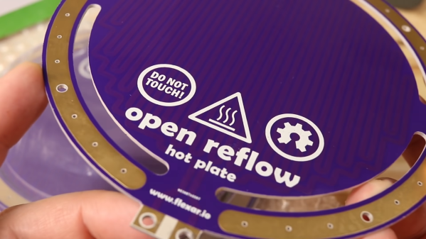
an up-close of the PCB hotplate

Using A PCB To Reflow PCBs – Take 2!

It’s not too hard to make your electronics project get warm. Design your traces too small, accidentally short the battery inputs together, maybe reverse the voltage going to your MCU. We’ve all cooked a part or two over the years. But what about making a PCB that gets hot on purpose? That’s exactly what [Carl Bugeja] did in his second revision of a PCB hot plate, designed to reflow other PCBs.

[Carl’s] first attempt at making a hot plate yielded lukewarm results. The board, which was a single snaking trace on the top of an aluminum substrate, did heat up as it was supposed to. However, the thin substrate led to the hot plate massively warping as it heated up, reducing the contact against the boards being soldered. On top of that, the resistance was much greater than expected, resulting in much lower heat output.

The new revision of the board is on a thicker substrate with much thicker traces, reducing the resistance from 36 ohms on the previous design to just 1 ohm. The thicker substrate, paired with a newer design with fewer slots, made for a much sturdier surface that did not bend as it was heated.

Continue reading “Using A PCB To Reflow PCBs – Take 2!”