Is there anything more discouraging to the reverse engineer than to see a black blob of epoxy applied directly to a PCB? We think not, because that formless shape provides no clue as to what chip lies beneath, and that means a lot of detective work if you’re going to figure out how to use this thing.
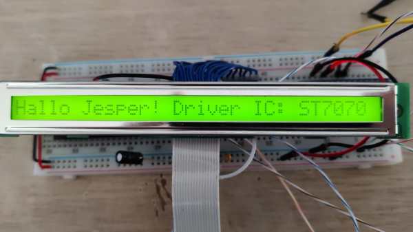
[Sudhir Chandra]’s detective story starts with a bunch of oddball LCDs, slim 1×32 character units rather than the more familiar 2×16 displays. Each bore the dreaded black COB blob on the back, as well as a handful of SMD components and not much else. Googling revealed no useful documentation, and the manufacturer wasn’t interested in fielding calls from a hobbyist. Reasoning that most manufacturers wouldn’t spin up a custom chip for every display, [Sudhir] assumed there was an ST7066, a common LCD driver chip, underneath the blob, especially given the arrangement of external components. But a jumper set was bodged together under this assumption didn’t get the display going.
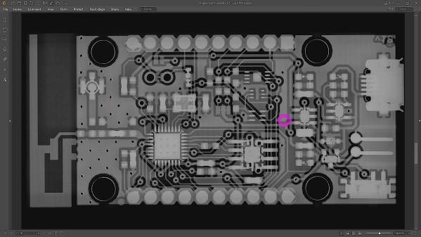
Next up were more destructive methods, to decap the COB and see what kind of numbers might be on the chip. Sandpaper worked at first, but [Sudhir] eventually turned to the “Chips a la [Antoine]” method of decapping, which uses heat and brute force to get at the goods. This got down to the chip, but [Sudhir]’s microscope wasn’t up to the task of reading the die markings.
What eventually cracked the case was tracing out the voltages across the various external resistors and matching them up to other chips in the same family as the ST7066, plus the realization that the long, narrow epoxy blob probably covered a similarly shaped chip, which led to the culprit: an ST7070. This allowed [Sudhir] to build an adapter PCB for the displays, with plans for a custom Arduino library to talk to the displays.
This was a great piece of reverse engineering and a good detective story to boot. Hats off to [Sudhir] for sticking with it.

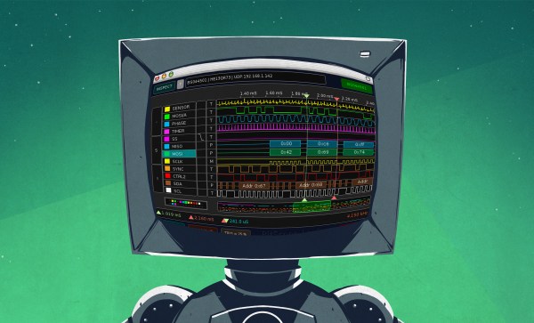
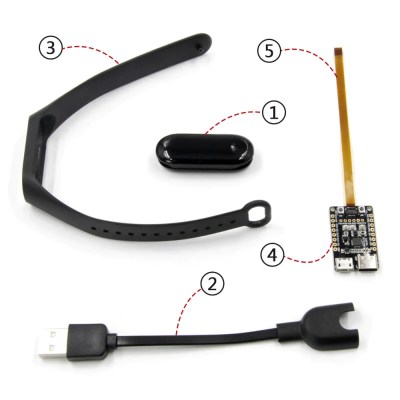 In this article, let’s figure out places where you can use a logic analyzer, and places where you can’t. We’ll start with the first limitation of logic analyzers – capture speed. For instance, here’s a cool thing you can buy on Aliexpress – a wristband from TTGO that looks like a usual fitness tracker, but has an ESP32 in it, together with an IMU, an RTC, and an IPS screen! The seller also has an FFC-connectable devboard for programming this wristband over UART, plus vibromotor and heartrate sensor expansion modules.