Week 1 of Hackaday’s Caption CERN Contest is complete. We have to say that the Hackaday.io users outdid themselves with funny captions but we also helped CERN add meaning to one of their orphan images. First a few of our favorite captions:
The Funnies:
If you adjust that scope again, when I haven’t touched the controls, I’m donating you to a city college. – [Johnny B. Goode]
SAFTEY FIRST – The proper way to test a 6kv power supply for ripple on the output. – [milestogoh]
Dr. Otto Gunther Octavius – R&D some years before the accident. – [jlbrian7]
The prize though, goes to Hackaday commenting superstar [DainBramage], who proved he knows us all too well with his Portal inspired caption:
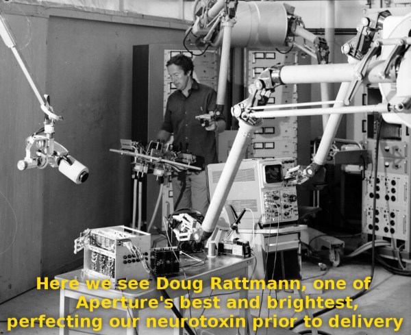
Here we see Doug Rattmann, one of Aperture’s best and brightest, perfecting our neurotoxin prior to delivery.
Congrats [DainBramage], enjoy your shirt from The Hackaday Store!
The Meaning of the Image:
 Funny captions weren’t the only thing in the comments though – the image tickled [jlbrian7’s] memory and led to a link for CERN Love. A four-year old blog entry about robots at CERN turned out to be the key to unraveling the mystery of this captionless photo. The image depicts [Robert Horne] working with a prototype of the MANTIS system. MANTIS was a teleoperation manipulator system created to work in sections of the CERN facility which were unsafe for humans due to high levels of radioactivity. The MANTIS story is an epic hack itself, so keep your eyes peeled for a future article covering it! We’ve submitted the information to CERN, and we’re giving [jlbrian7] a T-shirt as well for his contribution to finding the actual caption for this image.
Get Started on Next Week:
The image for week 2 is already up, so head over and see for yourself. We’re eager for your clever captions. Ideally we can also figure out the backstory for each week’s randomly chosen image.