The ancient art of sailing can be very intimidating for the uninitiated given the shifty nature of wind. To help understand the interaction of wind direction and board orientation, [KifS] designed a hands-on sailing demonstrator that lets students grasp the basics before setting foot on a real sailboat.
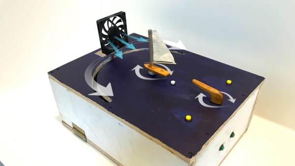
The demonstrator uses a potentiometer as a tiller to control a model sailboat’s angle, while another stepper motor adjusts the position of a fan to simulate changing wind directions. With an Arduino Uno controlling everything, this setup affords students the opportunity to learn about sail positioning and adjusting to shifting winds in an interactive way, without the pressures and variables of being on the water.
[KifS]’s creation isn’t just about static demonstrations. It features four modes that progressively challenge learners—from simply getting a feel for the tiller, to adjusting sails with dynamic wind changes, even adding a game element that introduces random wind movements demanding quick adjustments. [KifS] mentions there are potentials aspects that can be refined, like more realistic sail response and usability, but it already achieved the main project goals.
There are a myriad of potential ways to add new tech to the ancient art of sailing. We’ve seen a DIY autopilot system, full sensor arrays, and an open source chart plotter. It’s even been proven you can have a wind powered land vehicle that travels faster than the wind.