There’s no question that surface-mount technology has been a game-changer for PCB design. It means easier automated component placement and soldering, and it’s a big reason why electronics have gotten so cheap. It’s not without problems, though, particularly when you have no choice but to include through-hole components on your SMT boards.
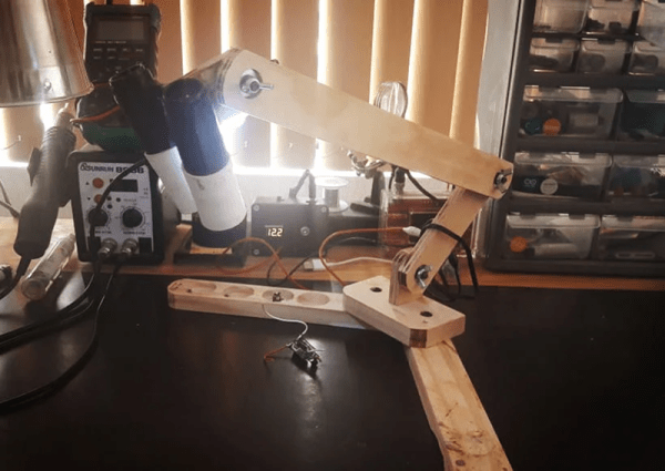
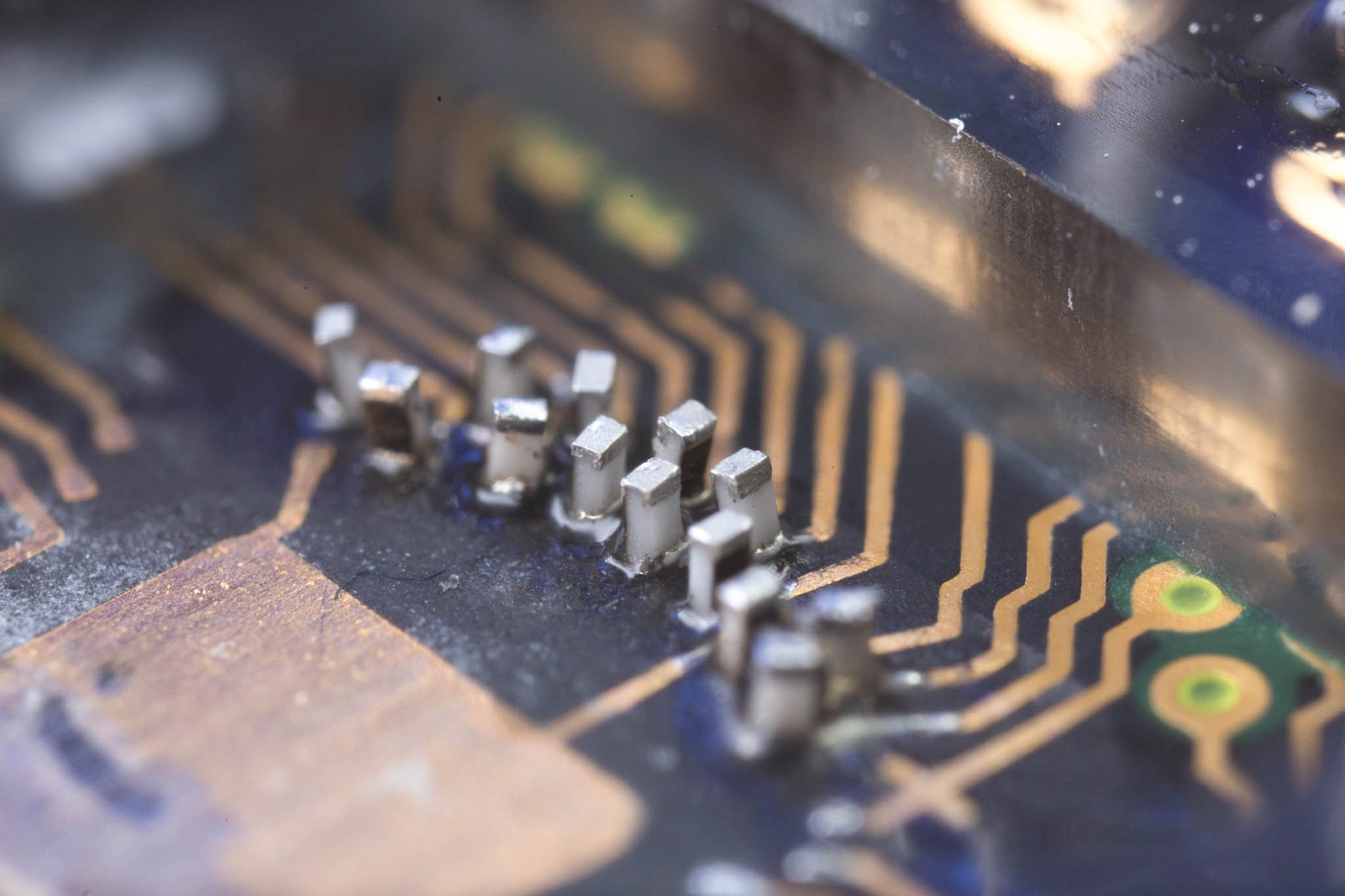
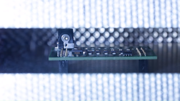
[James Clough] ran into this problem recently, and he tried to solve it by reflowing through-hole connectors onto assembled SMT boards. The boards are part of his electronic lead screw project, an accessory for lathes that makes threading operations easier and more flexible. We covered the proof-of-concept for the project; he’s come a long way since then and is almost ready to start offering the ELS for sale. The PCBs were partially assembled by the board vendor, leaving off a couple of through-hole connectors and the power jack. [James]’ thought was to run the boards back through his reflow oven to add the connectors, so he tried a few experiments first on the non-reflow rated connectors. The Phoenix-style connectors discolored and changed dimensionally after a trip through the oven, and the plastic on the pin headers loosened its grip on the pins. The female header socket and the power jack fared better, so he tried reflowing them, but it didn’t work out too well, at least for the headers. He blames poor heat conduction due to the lack of contact between the board and the reflow oven plate, and we agree; perhaps an aluminum block milled to fit snugly between the header sockets would help.
Hats off to [James] for trying to save his future customers a few steps on assembly, but it’s pretty clear there are no good shortcuts here. And we highly recommend the electronic leadscrew playlist to anyone interested in the convergence of machine tools and electronics.