Holiday Cheer From The ATtiny13

There are smaller microcontrollers than the ATtiny13. Some ARM chips will fit on the head of a large pin, and even in Atmel world, the ATtiny10 comes in a tiny SOT-23-6 package – a size normally reserved for surface mount transistors. The ‘tiny13, though, can be programmed with just about any ISP and comes in an 8-pin DIP. It’s the bare minimum if you’re looking to break out of the world of Arduino, and you can do some pretty cool things with it, like playing some holiday audio with an SPI Flash chip.

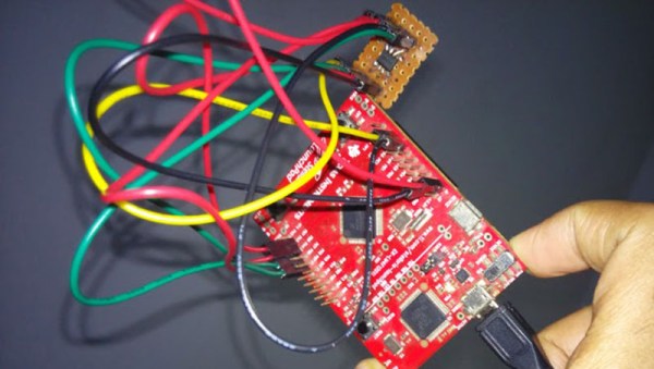
[Vinod] tried opening up a cheap camera pen, but in the course of disassembly a few traces broke. He was now left with a 4Mbit SPI Flash chip. This was obviously the time to investigate what could be done with a small microcontroller and a huge amount of Flash. and the Attiny13 audio player was born.

The circuit uses one PWM for audio out, and reads audio directly from the Flash chip. The UART on board the ‘tiny13 is used to update the Flash, and there’s also a switch to select between play and record. If you’re counting, that means there are 4 pins for the Flash, 2 pins for the UART, 1 for the switch, one for the audio output, and the power and ground rails, all in an 8-pin package. That’s a pretty cool way to use one pin for two different functions.

You can check out a video of the project in action below.

Continue reading “Holiday Cheer From The ATtiny13”

Digging Into The APA102 Serial LED Protocol

[Tim] got his hands on some APA102 RGB LEDs, which are similar in function to the common WS2812 addressable LEDs seen in many projects we’ve featured. The advantage of APA102 LEDs is that they don’t have the strict timing requirements of the WS2812. These LEDs are controlled with a SPI bus that can be clocked at any arbitrary rate, making them easy to use with pretty much any microcontroller or embedded system.

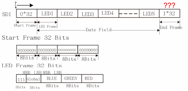
After working with the LEDs, [Tim] discovered that the LEDs function a bit differently than the datasheet led him to believe. [Tim] controlled a strand of APA102 LEDs with an ATtiny85 and connected a logic analyzer between some of the LEDs. He discovered that the clock signal of the SPI interface isn’t just passed through each LED, it actually looks like it’s inverted on the output. After some investigation, [Tim] found that the clock signal is delayed by a half period (which looks like an inversion) before it’s passed to the next LED. This gives the next LED in the strand enough time for data on the data line to become valid before latching it in.

Since the clock is delayed, [Tim] discovered that additional bits must be clocked as an “end frame” to generate clock signals which propagate the remaining data to the end of the strand. Although the datasheet specifies a 32-bit end frame, this only works for strings of up to 64 LEDs. More bits must be added to the end frame for longer strands, which the datasheet doesn’t even mention. Check out [Tim]’s post for more information, where he walks you through his logic analysis of the APA102 LEDs.

12 Mbps Communication Between A PC And MCU

The world of hobby electronics have only started putting USB in projects for the last few years, and right now, pushing 1.5 Mbps down a USB port is good enough for most cases. This isn’t true for all cases; that’s a terrible data rate, really, and to get the most out of a USB connection, you can at least move up to USB Full Speed and 12 Mbps.

[Linas] is using the STM32F4 microcontroller for this example, an extremely large and very capable chip. [Linas] is using FTDI’s FT2232D USB UART to send data from an SPI port over USB. This chip does support 12 Mbps, but only after a few additions; an external EEPROM must be connected to the FTDI chip to provide a USB 2.0 device descriptor, otherwise the connection between the microcontroller and a computer is limited to 1.5 Mbps. Even using the USB on the STM32 would be a bottleneck in this case; [Linas] is moving data out of the processor using only the DMA controller – using the USB on the STM32 would eat up processor cycles in the microcontroller.

Thanks to the DMA controller inside the STM32, the microcontroller is capable of sending and receiving data through SPI at the same time. The STM32 is capable of reading and writing to the Tx and Rx buffer at the same time, but the computer is only capable of half-duplex operation – it can only read or write at any one time. [Linas] is setting up the DMA controller on the STM32 as a circular mode, putting everything in the buffer into the FTDI chip, and reading everything sent from the computer back into the STM32’s memory. After counting off the correct number of packets. the controller resets everything, moves the circular buffer back to the beginning, and starts the whole process over again.

The circuit was prototyped with an STM Discovery board. With Labview, [Linas] can see the bits coming out of the microcontroller, and send some bits back to the micro over USB. [Linas] has an extraordinarily detailed video tutorial on this project. You can check that out below.

Continue reading “12 Mbps Communication Between A PC And MCU”

Better SPI Bus Design

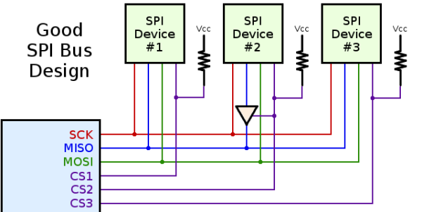
Quick, how do you wire up an SPI bus between a microcontroller and a peripheral? SCK goes to SCK, MISO goes to MISO, and MOSI goes to MOSI, right? Yeah. You’ll need to throw in a chip select pin, but that’s pretty much it. Just wires, and it’ll most likely work. Now add a second device. The naïve solution found in thousands of Arduino tutorials do the same thing; just wires, and it’ll probably work. It’s not that simple, and Mr. Teensy himself, [Paul Stoffregen] is here to show you why.

When using multiple SPI devices, a pullup resistor on the chip select lines are a really great idea. Without a pullup, devices will work great when used alone, but will inexplicably fail when used together. It’s not magic; both devices are listening to the bus when only one should be. Putting a pullup on the CS lines keeps everything at the right logic level until a device is actually needed.

How about the MISO line? Most peripherals will disconnect their pins when the chip select signal is active, but there are exceptions. Good luck finding them. There is an easy way to check, though: just connect two resistors so the MISO line floats to a non-logic level when the CS pin is high, and check with a voltmeter. If MISO is driven high or low, you should put a small tri-state buffer in there.

That just covers hardware, and there are a few things you can do in software to reduce the number of conflicts when using more than one SPI device. One of these methods is transactions, or defining the clock rate, setting MSB or LSB first, and the polarity of the clock. Newer versions of the Arduino SPI library support transactions and the setup is very easy. In fact, transaction support in the Arduino library is something [Paul] worked on himself, and gets around the problem of having SPI-related code happening in both the main loop of a program and whenever an interrupt hits. Awesome work, and a boon to the Arduino makers around the world.

Cheap Power Meter

Digital Data From A Cheap Power Meter

Power meters like the Kill-A-Watt are great for keeping track of energy usage, and are also very hackable. The Kill-a-Watt in particular puts out analog signals proportional to current and voltage, which makes it easy to interface with a microcontroller.

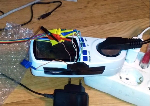
Although reading analog voltages is easy enough, [Kalle] found a cheap Chinese power meter that is even more hackable. These inexpensive power meters cost about the same as a first-generation Kill-a-Watt, but they directly stream out digital data. The power meter [Kalle] hacked has a non-US plug, but the meter is available from the usual suppliers (eBay, Aliexpress, etc) with a 3-prong US plug and 120v rating.

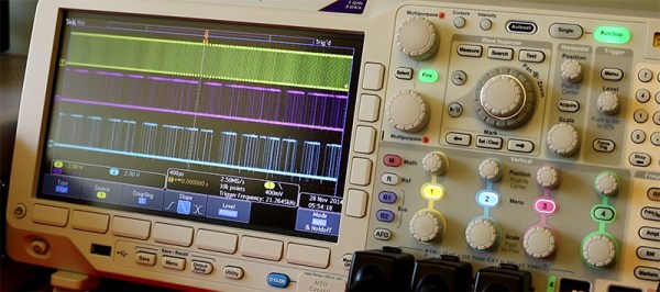
After breaking out a logic analyzer, [Kalle] discovered that the meter constantly streams voltage, current, and power data from the measurement board to the display board on a SPI-like bus. The ribbon cable inside the meter even has the clock and data bus lines clearly labelled. [Kalle] went on to reverse-engineer the protocol and write an Arduino sketch that parses the stream, making it even easier to integrate this meter into your next power monitoring project.

Strobe Remote

Reverse Engineering A Wireless Studio Lighting Remote

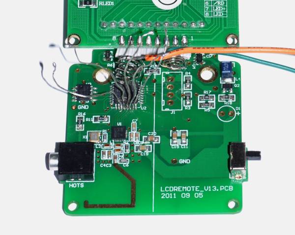
If you want to take a photograph with a professional look, proper lighting is going to be critical. [Richard] has been using a commercial lighting solution in his studio. His Lencarta UltraPro 300 studio strobes provide adequate lighting and also have the ability to have various settings adjusted remotely. A single remote can control different lights setting each to its own parameters. [Richard] likes to automate as much as possible in his studio, so he thought that maybe he would be able to reverse engineer the remote control so he can more easily control his lighting.

[Richard] started by opening up the remote and taking a look at the radio circuitry. He discovered the circuit uses a nRF24L01+ chip. He had previously picked up a couple of these on eBay, so his first thought was to just promiscuously snoop on the communications over the air. Unfortunately the chips can only listen in on up to six addresses at a time, and with a 40-bit address, this approach may have taken a while.

Not one to give up easily, [Richard] chose a new method of attack. First, he knew that the radio chip communicates to a master microcontroller via SPI. Second, he knew that the radio chip had no built-in memory. Therefore, the microcontroller must save the address in its own memory and then send it to the radio chip via the SPI bus. [Richard] figured if he could snoop on the SPI bus, he could find the address of the remote. With that information, he would be able to build another radio circuit to listen in over the air.

Using an Open Logic Sniffer, [Richard] was able to capture some of the SPI communications. Then, using the datasheet as a reference, he was able to isolate the communications that stored information int the radio chip’s address register. This same technique was used to decipher the radio channel. There was a bit more trial and error involved, as [Richard] later discovered that there were a few other important registers. He also discovered that the remote changed the address when actually transmitting data, so he had to update his receiver code to reflect this.

The receiver was built using another nRF24L01+ chip and an Arduino. Once the address and other registers were configured properly, [Richard’s] custom radio was able to pick up the radio commands being sent from the lighting remote. All [Richard] had to do at this point was press each button and record the communications data which resulted. The Arduino code for the receiver is available on the project page.

[Richard] took it an extra step and wrote his own library to talk to the flashes. He has made his library available on github for anyone who is interested.

WS2812 at 670 kHz

Driving WS2812B Pixels, With DMA Based SPI

Typically bit-banging an I/O line is the common method of driving the WS2812B (WS2811) RGB LEDs. However, this ties up precious microcontroller cycles while it waits around to flip a bit. A less processor intensive method is to use one of the built-in Serial Peripheral Interface (SPI) modules. This is done using specially crafted data and baud rate settings, that when shifted out over the Serial Data Out (SDO) pin, recreate the needed WS2812B signal timing. Even when running in SPI mode, your hardware TX buffer size will limit how many pixels you can update without CPU intervention.

[Henrik] gets around this limitation by using peripheral DMA (Direct Memory Access) to the SPI module in the Microchip PIC32MX250F128B microcontroller. Once properly configured, the DMA controller will auto increment through the defined section of DMA RAM, sending the pixel data over to the SPI module. Since the DMA controller takes care of the transfer, the micro is free to do other things. This makes all of DMA memory your display buffer. And leaves plenty of precious microcontroller cycles available to calculate what patterns you want the RGB LEDs to display.

Source code is available at the above link for those who would like to peruse, or try it out. This is part of [Henrik’s] Pixel Art Project. Video of DMA based SPI pixels after the break:

Continue reading “Driving WS2812B Pixels, With DMA Based SPI”