In years gone by, trying out a new circuit probably would have meant heating up a soldering iron. Solderless breadboards have made that even easier and computer simulation is easier still, but there’s something not quite as satisfying about building a circuit virtually. [Thedeuluiz] has a way to get some of the best of both worlds with the RTSpice project.
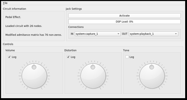
The idea is simple in concept, although not as simple in execution. The program does a Spice-like simulation of a circuit and can accept input and produce output from a PC’s sound card. Obviously, that means you can’t simulate RF circuits — at least not at the input and the output. It also means the simulation has to run lightning fast to keep up with the sound card sample rate. According to the author, it works best with modest circuits but exactly how big you can go will depend on your hardware.