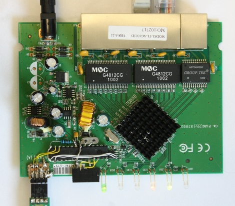
Wireless RGB Light Bulb

img_3953

Want to make the above yourself? [Sprite_tm] did a thorough job documenting the build step by step (complete with pics, schematics, graphs, and links to the parts used). In summary, [Sprite_tm] busted open an Ikea CFL bulb to reuse the housing. Inside, he installed a scavenged power supply, ATtiny44, RGB LED module, and a radio receiver. A remote control allows [Sprite_tm] to change the lighting of his room to nearly any color. The cost of the project is a little under $30. The price tag isn’t so steep when one considers the insanely long lifetime of LEDs.

AVR Boost Converter

avrboost

Over at SpriteMods, [sprite_tm] realized that a microcontroller could be used as a boost converter to power itself. A boost converter steps up voltage from a battery by switching the output of a coil. First, it is tied to ground so a magnetic field can build up in the coil. It is then released as a higher voltage than the input. Normally dedicated chips do this at an incredibly high frequency, but the PWM signal from an AVR works well enough. This can be used in low-power situations where space is an issue.

[via EMSL]

Controllable Bristlebot

[sprite_tm], whose projects we have covered in the past, took the popular bristlebot to an extreme and created a controllable version. A bristlebot consists of a small vibrating motor mounted with a battery on the head of a toothbrush. These micro-robots buzz around randomly, and he attempted to tame them. He used a platform of twin bristlebots and added an optical sensor from a laser mouse and an ATtiny13. The optical sensor is used to determine the relative motion of the robot, so that the motors can be adjusted accordingly. He also has a video of the bot using the sensor to find a mark on the floor and stay within bounds. Although it isn’t as accurate, it acts like a traditional line-following robot.

Continue reading “Controllable Bristlebot”

Working With VFDs

vfd

We love old display technology, like Nixie tubes, but they’re often difficult to work with because they require higher voltages than digital logic. Vacuum florescent displays (VFD) fall into this category. While not necessarily “old”, they are becoming far less common than LCDs. The main benefit of a VFD is that it actually produces light directly; it doesn’t require a backlight. You’ll find these displays on various players and appliances: CD, DVD, VCR, microwaves, stoves, car headunits, and others.

[Sprite_tm] had written off some VFDs, but recently revisited them with renewed interest. He started by testing what sort of voltage would be required to drive the display. It took 3V for the filament plus 15V to drive the grids. There are VFD controller chips available, but he wanted to get this working with what he had on hand. He had experience with older 40xx series logic, which can be powered by much higher voltages than 5V 74xx. His final schematic has three 4094 serial to parallel chips with an ATtiny2313 controller. A 5V power supply is dropped to 3V with diodes to drive the filament while a boost converter brings it up to 15V for the 4094s that switch the segments. While the code is specific to this display, it would be a great place to start your own project.

Overhauling LED Marquees

led-sign

In a previous job, [sprite_tm] was responsible for wrangling many different LED text ad marquees. The hardware was fairly simple and he always figured they could be pushed much further with a little work. He recently acquired ten 32×16 LED displays a decided to see what he could do with them. By the end of the project, he had full motion video running on the display. This is a great project to read up on if you’ve ever wondered about LED matrix displays. He starts by reverse engineering the electronics on the board. He then attached an ATmega88 to drive the display module. Multiple display modules were daisy chained together over serial. The article covers PWM control and refresh timing as well. Check out one of a few demo videos below. Continue reading “Overhauling LED Marquees”

Minimalist LED Light Detecting Candle

[youtube=http://www.youtube.com/watch?v=sPe5RtUOOdc]

Our flickering LED circuit combined two known circuit, and certainly wasn’t graceful because of it. [sprite_tm] saw quite a few areas where the circuit could be reduced. He ended up taking it down to just two LEDs, a battery, and an ATtiny13. The first step was getting rid of the current limiting resistors. The datasheet shows that with a 3V supply the AVR will limit the current well below the maximum current. The light sensor was removed next. [sprite_tm] referenced an earlier post on sensing with LEDs. He measures the voltage across one of the LEDs while it is off to see how much light is hitting it. The current draw while on is 10mA and 50uA while off.