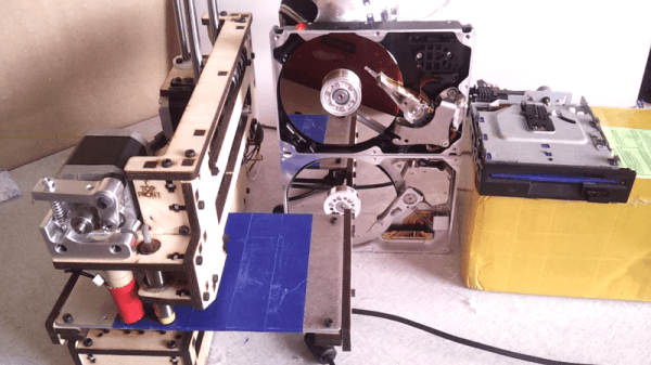
Like many of us, [Laurens] likes video game music and bending hardware to his will. Armed with a Printrbot, a couple of floppy drives, and some old HDDs, he built the Unconventional Instrument Orchestra. This 2015 Hackaday Prize contender takes any MIDI file and plays it on stepper and solenoid-based hardware through a Java program.
A while back, [Laurens] won a Fubarino in our contest by using a MIDI keyboard and an Arduino to control the Minecraft environment with Legend of Zelda: Ocarina of Time songs. The Unconventional Instrument Orchestra uses that Fubarino of victory to control the steppers of two floppy drives. He only needed three pins to control the drives—one to enable, one to set the head’s direction, and one to make it step once per pulse.
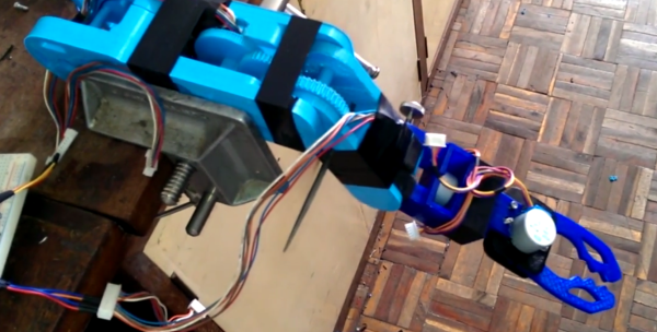
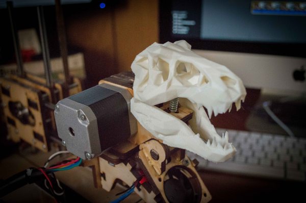
If ever you’ve been around a 3D printer, you know they make music as a natural side effect. The problem is getting the printer to obey the rests in a piece of music. In order to do this, [Laurens] used his software to control the printer, essentially withholding the next command until the appropriate time in the song.
The percussive elements of this orchestra are provided by a hard drive beating its head against the wall. Since it’s basically impossible to get an HDD to do this as designed (thankfully), [Laurens] replaced the control board with a single transistor to drive the coil that moves the head.
[Laurens] has made several videos of the orchestra in concert, which are a joy all their own. Most of the visual real estate of each video is taken up with a real-time visualization of the music produced by the software. There’s still plenty of room to show the orchestra itself, song-specific gameplay, and a textual commentary crawl in 16-segment displays. Check out the playlist we’ve embedded after the break.
Continue reading “Hackaday Prize Entry: Orchestral Invention Defies Convention” →