Some of the first popular printers that made it into homes and schools were Apple Imagewriters and other deafeningly slow dot matrix printers. Now there’s a laser printer in every office that’s whisper quiet, fast, and produces high-quality output that can’t be matched with dot matrix technology.
In case you haven’t noticed, 3D printers are very slow, very loud, and everyone is looking forward to the day when high-quality 3D objects can be printed in just a few minutes. We’re not at the point where truly silent stepper motors are possible just yet, but with the Trinamic TMC2100, we’re getting there.
Most of the stepper motors you’ll find in RepRaps and other 3D printers are based on the Allegro A498X series of stepper motor drivers, whether they’re on breakout boards like ‘The Pololu‘ or integrated on the control board like the RAMBO. The Trinamic TMC2100 is logic compatible with the A498X, but not pin compatible. For 99% of people, this isn’t an issue: the drivers usually come soldered to a breakout board.
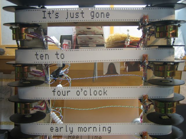
There are a few features that make the Trinamic an interesting chip. The feature that’s getting the most publicity is a mode called stealthChop. When running a motor at medium or low speeds, the motor will be absolutely silent. Yes, this means stepper motor music will soon be a thing of the past.
However, this stealthChop mode drastically reduces the torque a motor can provide. 3D printers throw around relatively heavy axes fairly fast when printing, and this motor driver is only supposed to be used at low or medium velocities.
The spreadCycle feature of the TMC2100 is what you’ll want to use for 3D printers. This mode uses two ‘decay phases’ on each step of a motor to make a more efficient driver. Motors in 3D printers get hot sometimes, especially if they’re running fast. A more efficient driver reduces heat and hopefully leads to more reliable motor control.
In addition to a few new modes of operation, the TMC2100 has an extremely interesting feature: diagnostics. There are pins specifically dedicated as notification of shorted outputs, high temperatures, and undervolt conditions. This is something that can’t be found with the usual stepper drivers, and it would be great if a feature like this were to ever make its way into a 3D printer controller board. I’m sure I’m not alone in having a collection of fried Pololu drivers, and properly implementing these diagnostic pins in a controller board would have saved those drivers.
These drivers are a little hard to find right now, but Watterott has a few of them already assembled into a Pololu-compatible package. [Thomas Sanladerer] did a great teardown of these drivers, too. You can check out that video below.