Making A Unique Type Of Wind Gauge For Home Assistant Use

Sometimes, it’s nice to know how windy it is outside. Knowing the direction of the wind can be a plus, too. To that end, [Sebastian Sokołowski] built himself an unusual anemometer—a wind gauge—to feed into his smart home system.

[Sebastian’s] build is able to tell both wind speed and direction—and with no moving parts! Sort of, anyway. That makes the design altogether different from the usual cup type anemometers with wind vanes that you might be used to seeing on home weather stations. [Sebastian] wanted to go a different route—he wanted a sensor that wouldn’t be so subject to physical wear over time.

The build relies on strain gauges. Basically, [Sebastian] 3D printed a sail-like structure that will flex under the influence of the wind. With multiple strain gauges mounted on the structure, it’s possible to determine the strength of the wind making it flex and in what direction. [Sebastian] explains how this is achieved, particularly involving the way the device compensates for typical expansion and contraction due to temperature changes.

It’s a really unique way to measure wind speed and direction; we’d love to learn more about how it performs in terms of precision, accuracy, and longevity—particularly with regards to regular mechanical and ultrasonic designs. We’ll be keeping a close eye on [Sebastian’s] work going forward. Video after the break.

Continue reading “Making A Unique Type Of Wind Gauge For Home Assistant Use”

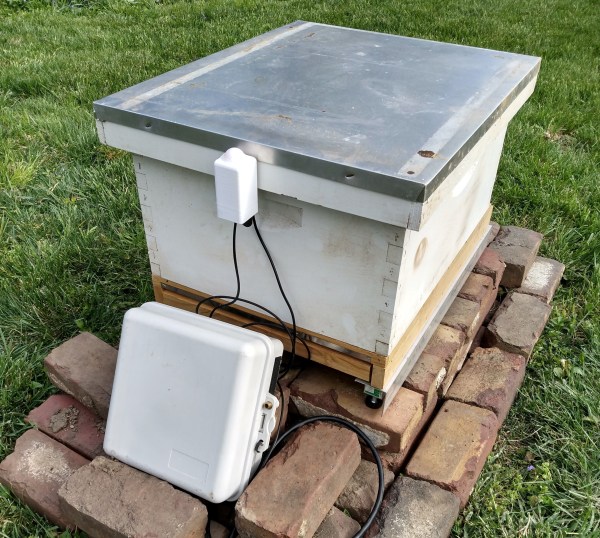
A beehive sits on bricks with an outdoor-rated box full of electronics to monitor the hive.

Hive Monitor Is The Bee’s Knees

Beekeeping is quite the rewarding hobby. There’s delicious honey and useful wax to be had, plus you get the honor of knowing that you’re helping to keep the bee population surviving and thriving. [Ben Brooks] likes to keep tabs on the hive, but doesn’t like the idea of opening it up more often than necessary. After a couple of beekeeping rodeos, [Ben] decided to build his own tracker to get reports on the health and the activity of the hive through Home Assistant.

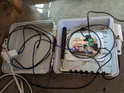
A white outdoor-rated box opened to reveal electronics to monitor a beehive.This hive tracker features a light sensor, a temperature sensor, and three strain gauges to measure the weight. There would be four, but a mouse decided to take a bite of the wires in the most nightmarish place to repair.

Everything runs off of an ESP32, and there’s an external antenna involved because the hive is nearly out of Wi-Fi range. The strain gauges are the affordable bathroom-scale type, and [Ben] has extras for if and when the number of hives goes up.

We like the combination of hard work and simplicity going on here — [Ben] milled and drilled the PCB himself, and used phone plugs to connect the temperature and weight sensors. Unfortunately, the plugs make the strain gauges a little finicky, so [Ben] says he would probably use screw terminals next time, or might be soldering the wires sooner rather than later. Consider this one a work in progress, and keep watching for updates as [Ben] works out the kinks.

Interested in beekeeping, but don’t want to build a traditional hive? Check out this beehive in a bottle.

Weird Things To Do With FPGAs

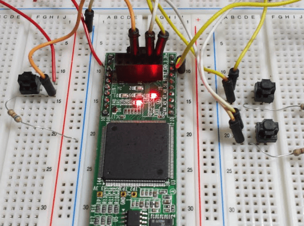
There’s an old joke about how can you find the height of a building using a barometer. One of the punchlines is to drop the barometer from the roof and time how long it takes to hit the ground. We wonder if [Alexlao512] had that in mind when he wrote a post about unconventional uses of FPGAs. Granted, he isn’t dropping any of them off a roof, but still. The list takes advantage of things we usually try to avoid such as temperature variation, metastability, and the effects of propagation delays.

For example, you probably know that hooking up an odd number of inverters into a loop forms an oscillator—the so-called ring oscillator. The post discusses how you can use an oscillator like that to measure propagation delay or even as a strain gauge. If you put pressure on the FPGA chip, the frequency of the ring oscillator will subtly vary.

Continue reading “Weird Things To Do With FPGAs”

Exploring Woodworking Mysteries With Strain Gauges And Raspberry Pi

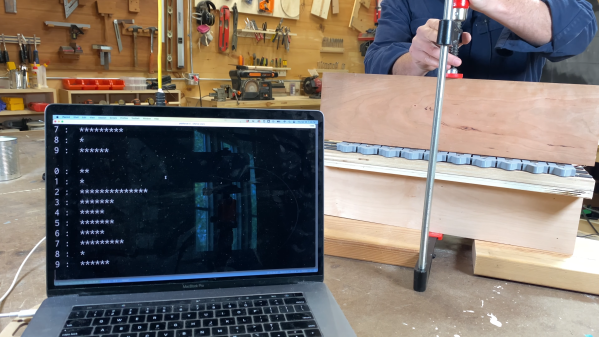
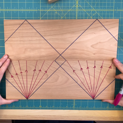
If you’re not a woodworker, you might not have heard of the “45-degree rule.” It goes like this: a clamp exerts a force that radiates out across a triangular region of the wood that forms a right angle — 45 degrees on each side of the clamp’s point of contact. So, to ensure that force is applied as evenly as possible across the entire glue joint, clamps should be spaced so that these force triangles overlap. It’s a handy rule, especially for the woodworker looking to justify the purchase of more clamps; you can never have too many clamps. But is it valid?

Myth busted?

The short answer that [ari kardasis] comes up with in the video below is… sort of. With the help of a wonderfully complex array of strain gauges and a Raspberry Pi, he found that the story isn’t so simple. Each strain gauge lives in a 3D printed bracket that spaces the sensors evenly along the wood under test, with a lot of work going into making the test setup as stiff as possible with steel reinforcement. There were some problems with a few strain gauges, but once he sorted that out, the test setup went into action.

[ari] tested clamping force transmission through pieces of wood of various widths, using both hardwoods and softwoods. In general, he found that the force pattern is much broader than the 45-degree rule suggests — he got over 60 degrees in some cases. Softwoods seemed to have a somewhat more acute pattern than hardwoods, but still greater than the rulebook says. At the end of the day, it seems like clamp spacing of two board widths will suffice for hardwoods, while 1.5 or so will do for softwoods. Either way, that means fewer clamps are needed.

A lot of woodworking is seat-of-the-pants stuff, so it’s nice to see a more rigorous analysis like this. It reminds us a lot of some of the experiments [Matthia Wandel] has done, like load testing various types of woods and glues.

Continue reading “Exploring Woodworking Mysteries With Strain Gauges And Raspberry Pi”

Haptick: The Strain Gauge Based 6DoF Controller

Six degrees of freedom (6DoF) controllers are used for manipulating an object in a CAD or 3d modeling program and are often called spacemice. You can twist it, push it, and even bop it. Most work with optical encoders, shining an LED through a slit to some form of photodetector on the other side. [Matthew Schubert] wanted to make his own spacemouse, but had some new ideas of how to go about it. His two-part project, dubbed haptic, focuses on measuring the forces, not the displacement.

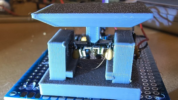
He decided to try thick-film resistors as strain gauges and revisit load cells and proper strain gauges later. The actual structure quickly converged on the Stewart Platform, formed from three custom PCBs. A base to sit on, a knob for the top, and a middle board designed to take the strain with SMD resistors. A Teensy 3.2 talks to the ADS131M06 ADC and streams 4k samples per second to the host computer via serial. For prototyping, the calculations were done on the PC. Continue reading “Haptick: The Strain Gauge Based 6DoF Controller”

PCB Gets Weighty Assignment

[Curious Scientist] tried building an integrated strain gauge on a PCB, but ran into problems. Mainly, the low resistance of the traces didn’t show enough change under strain to measure easily. Even placing a proper strain gauge on the PCB had limitations. His new design uses a bridge design to make the change in the gauges usefully large. You can see a video of the project below.

Bridging strain gauges isn’t a new idea. However, the novelty of this design is that the PCB has cantilever beams that facilitate the weighing. Standoffs mount a plate to the beams so that weight on the plate cause deformation on the beam that the strain gauges can measure.

Continue reading “PCB Gets Weighty Assignment”

A repair stand for bicycles with an integrated scale

DIY Repair Stand Holds Your Bike And Weighs It

If you’ve ever done maintenance or repair work on your bicycle, you’ll know that positioning a bike in your workshop isn’t trivial. You can use your bike’s kickstand, or lean it against a wall, but then you can’t work on the wheels. You can place it upside-down, but then the shifters and brake levers are hard to reach. You can hang it from the ceiling, but then you first need to install hooks and cables in hard-to-reach places. Ideally you’d want to have one of those standing clamp systems that the pros use, but their price is typically beyond a hobbyist’s budget.

Or at least, that’s how it used to be. As [Dane Kouttron] discovered, a simple wall-mounted bike clamp can be had for as little as $35 on eBay, and can easily be converted into a smart mobile repair stand. [Dane] fashioned an adjustable stand from some steel pipes he had lying around, and 3D-printed an adapter bracket to mount the bike clamp on it. This worked fine, but why stop at a simple clamp when you can expand it with, say, an integrated scale to weigh your bikes while you work on them? Continue reading “DIY Repair Stand Holds Your Bike And Weighs It”