[Pat]’s friend got a Pono for Christmas, a digital audio player that prides itself on having the highest fidelity of any music player. It’s a digital audio device designed in hand with [Neil Young], a device that had a six million dollar Kickstarter, and is probably the highest-spec audio device that will be released for the foreseeable future.
The Pono is an interesting device. Where CDs have 16-bit, 44.1 kHz audio, the Pono can play modern lossless formats – up to 24-bit, 192 kHz audio. There will undoubtedly be audiophiles arguing over the merits of higher sampling rates and more bits, but there is one way to make all those arguments moot: building an MP3 player out of an oscilloscope.
Digital audio players are limited by the consumer market; there’s no economical way to put gigasamples per second into a device that will ultimately sell for a few thousand dollars. Oscilloscopes are not built for the consumer market, though, and the ADCs and DACs in a medium-range scope will always be above what a simple audio player can manage.
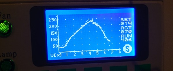
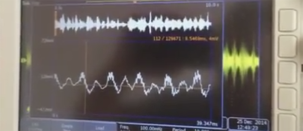
[Pat] figured the Tektronicx MDO3000 series scope sitting on his bench would be a great way to capture and play music and extremely high bit rates. He recorded a song to memory at a ‘lazy’ 1 Megasample per second through analog channel one. From there, a press of the button made this sample ready for playback (into a cheap, battery-powered speaker, of course).
Of course this entire experiment means nothing. the FLAC format can only handle a sampling rate of up to 655 kilosamples per second. While digital audio formats could theoretically record up to 2.5 Gigasamples per second, the question of ‘why’ would inevitably enter into the minds of audio engineers and anyone with an ounce of sense. Short of recording music from the master tapes or another analog source directly into an oscilloscope, there’s no way to obtain music at this high of a bit rate. It’s just a dumb demonstration, but it is the most expensive MP3 player you can buy.