We last covered the project when he had, unfortunately, wrecked the thing in a remote-controlled test flight. He later discovered that the motor’s crankshaft bearings had, well, exploded. The resulting shrapnel destroyed the motor and crashed the drone. He described this failure mode as “concerning”.
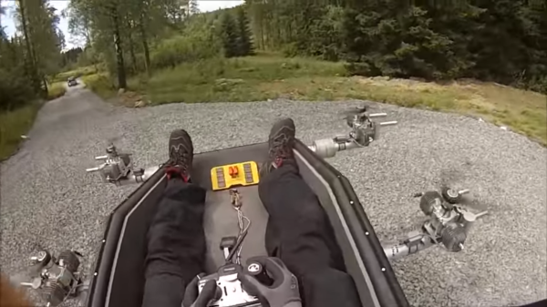
Also concerning is the act of stepping into the seat once all the propellers are started up. He tags this as “watch your step or die”. Regardless, he also describes flying in the thing as so incredibly fun that it’s hard to stay out of it; like a mechanical drug. It explains why his channel has been lately dominated by videos of him testing the multicopter. Those videos are found after the break.
The device drinks 0.65-0.7 liters per minute of gasoline, and he’s been going through reserves working out all the bugs. This means everything from just figuring out how to fly it to discovering that the dust from the ground effect tends to clog up the air filters; which causes them to run lean, subsequently burning up sparkplugs. Dangerous, but cool.
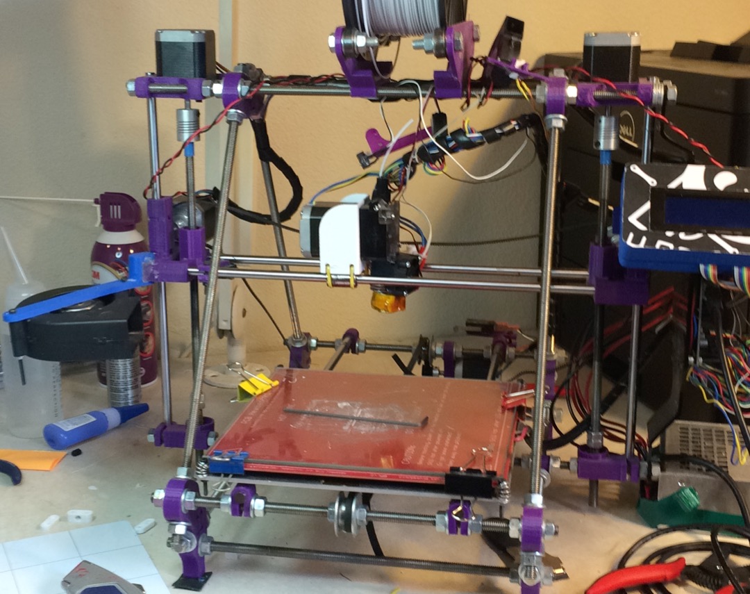
After years of cutting my hands on the exposed threads of my Prusa Mendel i2, it was time for a long overdue upgrade. I didn’t want to just buy a new printer because it’s no fun. So, I decided to buy a new frame for my printer. I settled on the P3Steel, a laser cut steel version of the Prusa i3. It doesn’t suffer from the potential squaring problems of the vanilla i3 and the steel makes it less wobbly than the acrylic or wood framed printers of similar designs.
My trusty i2. Very sharp. It… uh.. grew organically.
I expected a huge increase in reliability and print quality from my new frame. I wanted less time fiddling with it and more time printing. My biggest hope was that switching to the M5 threaded screw instead of the M8 the i2 used would boost my z-layer accuracy. I got my old printer working just long enough to print out the parts for my new one, and gleefully assembled my new printer.
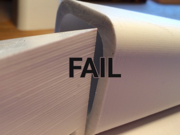
I didn’t wait until all the electronics were nicely mounted. No. It was time. I fired it up. I was expecting the squarest, quietest, and most accurate print with breathtakingly aligned z-layers. I did not get any of that. There was a definite and visible ripple all along my print. My first inclination was that I was over-extruding. Certainly my shiny new mechanics could not be at fault. Plus, I built this printer, and I am a good printer builder who knows what he’s doing. Over-extruding looks very much like a problem with the Z-axis. So, I tuned my extrusion until it was perfect.
Despite tuning my extruder steps perfectly, and getting good results instantly on larger prints. I was still having a ton of trouble with smaller parts. PLA is the favored printing material for its low odor, low warping, and decent material properties. It also has many downside, but it’s biggest, for the end user, lies in its large glass transition temperature range. Like all thermoplastics, it shrinks when it cools, but because of this large range, it stays expanded and, getting deep into my reserve of technical terms, bendy for a long time. If you don’t cool it, the plastic will pile up in its expanded state and deform.
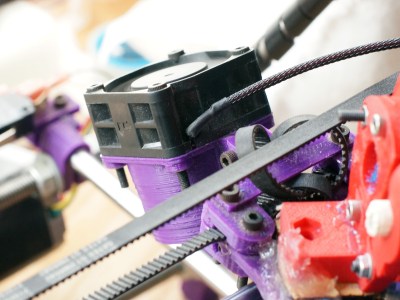
The old cooling fan on my trusty and thoroughly battered Prusa i2.
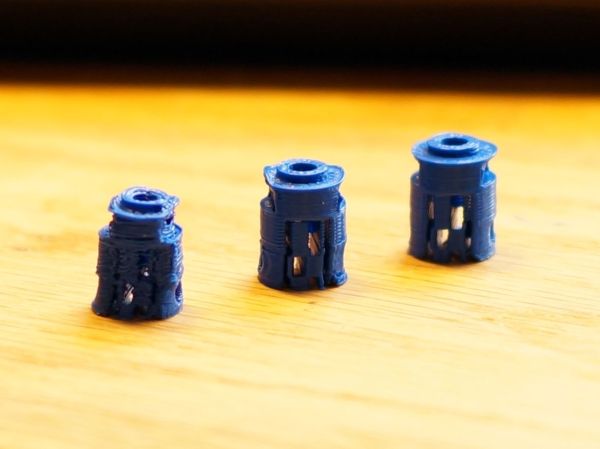
I am working on a project that needs a tiny part, pictured above. The part on the left is what I was getting with my current cooling set-up and temperature settings. It had very little semblance with the CAD file that brought it into this world.
The bond between layers in a 3d print occurs when the plastic has freshly left the nozzle at its melting point. Almost immediately after that, the plastic crosses from the liquid state into a glass state, and like pressing two pieces of glass together, no further bonding occurs. This means that in order to get a strong bond between the print layers, the plastic has to have enough thermal mass to melt the plastic below it. Allowing the polymer chains to get cozy and hold hands. Nozzle geometry can help some, by providing a heat source to press and melt the two layer together, but for the most part, the fusing is done by the liquid plastic. This is why large diameter nozzles produce stronger parts.
What I’m getting at is that I like to run my nozzle temperature a little hotter than is exactly needed or even sensible. This tends to produce a better bond and sometimes helps prevent jamming (with a good extruder design). It also reduces accuracy and adds gloopiness. So, my first attempt to fix the problem was to perhaps consider the possibility that I was not 100% right in running my nozzle so hot, and I dropped the temperature as low as I could push it. This produced a more dimensionally accurate part, but a extraordinarily weak one. I experimented with a range of temperatures, but found that all but the lowest produced goopy parts.
After confirming that I could not get a significant return on quality by fine tuning my temperature, I reduced the speed of the nozzle by a large percentage. By reducing the speed I was able to produce the middle of the three printed parts shown in the opening image. Moving the nozzle very slowly gave the ambient air and my old cooling fan plenty of time to cool the part. However, what was previously a five minute part now took twenty minutes to print. A larger part would be a nightmare.
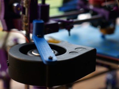
This will do.
So, if I can’t adjust the temperature to get what I want, and I can adjust the speed; this tells me I just need to cool the part better. The glass state of the plastic is useless to me for two reasons. One, as stated before, no bonding occurs. Two, while the plastic remains expanded and bendy, the new layer being put down is being put down in the wrong place. When the plastic shrinks to its final dimension is when I want to place the next layer. Time to solve this the traditional way: overkill.
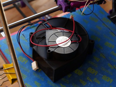
A while back my friend gifted me a little squirrel cage fan he had used with success on his 3d printer. Inspired by this, I had also scrounged a 12v, 1.7A fan from a broken Power Mac G5 power supply. When it spins up I have to be careful that it doesn’t throw itself off the table.
I should have added a rib to this bracket, this fan is heavy!
I printed out mounts for the fans. The big one got attached to the Z axis, and the little one rides behind the extruder. I fired up the gcode from before and started to print, only to find that my nozzle stopped extruding mid way. What? I soon discovered I had so much cooling that my nozzle was dropping below the 160C cold extrusion cut-off point and the firmware was stopping it from damaging itself. My heated bed also could no longer maintain a temperature higher than 59C. At this point I felt I was onto something.
I wrapped my extruder in fiberglass insulation and kapton tape, confidently turned the nozzle temperature up, set the speed to full, and clicked print. With the addition of the overkill cooling I was able to get the part shown to the right in my three example prints. This was full speed and achieved full bond. Not bad! Thus concludes this chapter in my adventures with cooling. I was really impressed by the results. Next I want to try cooling ABS as it prints. Some have reported horrible results, others pretty good ones, I’m interested. I also wonder about cooling the plastic with a liquid at a temperature just below the glass state as it is deposited. Thoughts?
To get the best power transfer into an antenna, tuning is required. This process uses a load to match the transmission line to the antenna, which controls the standing wave ratio (SWR).
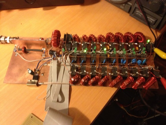
[k3ng] built his own automatic antenna tuner. First, it measures the SWR of the line by using a tandem match coupler. This device allows the forward and reflected signals on the line to be extracted. They are buffered and fed into an Arduino for sampling. Using this data, the device can calculate the SWR. The RF signal is also divided and sampled to measure frequency.
To automate tuning, an Arduino switches a bank of capacitors and inductors in and out of the circuit. By varying the load, it can find the ideal matching for the given antenna and frequency. Once it does, the settings are stored in EEPROM so that they can be recalled later.
After the break, check out a video of the tuner clicking its relays and matching a load.
Lots of readers are into toying around with RF and ham radios. One thing that is always of concern is tuning the antenna. New equipment is never cheap, so whenever another option comes along that uses existing test gear it gets our attention. [Alan Wolke] aka [w2aew] covers a process he uses to tune his HF antenna using a signal generator and oscilloscope.
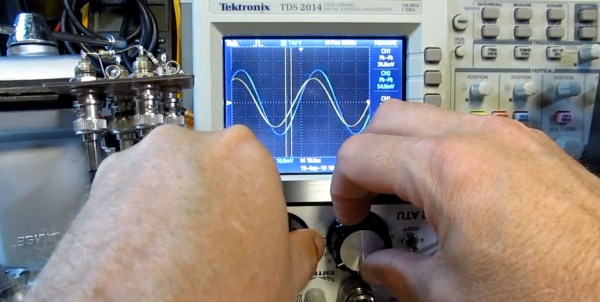
The process is more of a teaching aid than a practical replacement for commercial equipment mostly because proper signal generators and oscilloscopes are large items and sometimes not available or affordable. That said, if you do have such test gear you only need build a simple breakout board containing a form of wheatstone bridge where the unknown Rx is the antenna. Two oscilloscope probes are connected across the bridge balance nodes. Some special care needs to be taken matching probe cable length and 50 ohm input impedance to the oscilloscope. A couple of 1K probe coupling resistors are also needed to prevent affecting the impendence at the hookup points. Once the selected signal is injected you can adjust an antenna tuner until the two voltage waveforms match on the oscilloscope indicating your antenna network is tuned to 50 ohm impedance with no reactance.
Being able to tune your antenna visually can really help you understand what is going on in the turning process; matching not only input impedance but also phase shift indicating inductive or capacitive reactance. Join us after the break to see the video and for information on what’s presented in the second part of [Alan’s] presentation.