THP Entry: A CPLD Video Card With VGA And NTSC

NTSC

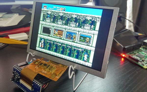
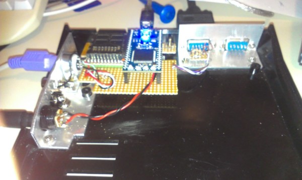
[PK] is working on a very simple video card, meant to output 640×480 VGA with a cheap CPLD. The interface will be 5 Volt SPI, meaning there’s a ton of potential here for anyone wanting put a reasonable (and cheap) display in a microcontroller project. The project has come a long way, and his latest update showcases something that has only been done once before: color NTSC with programmable logic

The brains of the outfit is a $5, 100-pin CPLD from Xilinx. Apart from that, the rest of the components are a crystal, PLL, and an almost hilarious number of resistors for the R2R ladder. The one especially unique component is the 25.056815 MHz crystal – multiply by that by two, and it’s fast enough to drive a VGA monitor. Divide the crystal by seven, it’s the 3.579545 MHz you need for an NTSC colorburst frequency. That’s VGA and NTSC in a single programmable logic project, something the one FPGA project we could find that did color NTSC couldn’t manage.

The next step in the project is designing a PCB and figuring out the code for the framebuffer. [PK] put up a demo showing off both VGA and NTSC; you can check that out below.


SpaceWrencherThe project featured in this post is an entry in The Hackaday Prize. Build something awesome and win a trip to space or hundreds of other prizes.

Continue reading “THP Entry: A CPLD Video Card With VGA And NTSC”

I2C From Your VGA Port

Breakout board for VGA to I2C

VGA, DVI, and HDMI ports use Display Data Channel (DDC) to communicate with connected displays. This allows displays to be plug and play. However, DDC is based on I2C, which is used in all kinds of electronics. To take advantage of this I2C port on nearly every computer, [Josef] built a VGA to I2C breakout.

This breakout is based on an older article about building a $0.25 I2C adapter. This adapter hijacks specific lines from the video port, and convinces the kernel it’s a standard I2C device. Once this is done, applications such as i2c-tools can be used to interact with the port.

[Josef] decided to go for overkill with this project. By putting an ATmega328 on the board, control for GPIOs and LEDs could be added. Level shifters for I2C were added so it can be used with lower voltage devices. The end product is an I2C adapter, GPIOs, and LEDs that can be controlled directly from the Linux kernel through an unused video port.

640×480 VGA On An Arduino

There are dozens, if not hundreds of examples around the Intertubes of an Arduino generating a VGA video output. The Arduino isn’t the fastest chip by far, and so far, all of these VGA generation techniques have peaked out at lower resolutions if you want to control individual pixels.[PK] has an interesting technique to generate 640×480 VGA at 60 frames per second without overclocking. It’s hacky, it’s ugly, but surprisingly, it actually works.

The VGA standard of 640×480 @ 60 fps requires pixels to be clocked out at 25.175 MHz, and the ATMega chips found in Arduinos top out at 20 MHz. [PK] wanted to generate VGA signals without overclocking, He did this by doubling the clock frequency with digital logic. The ATMega generates a clock, an inverter delays that clock so it is 90 degrees out of phase, and the two clocks are XORed, doubling clock output of the micro. It produces a very ugly square wave at 32 MHz – an error of 27% compared to the VGA spec. Somehow it still works.

With a hilariously out of spec clock, the rest of the project was pulled together from [Nick Gammon]’s VGA library, a 16×16 font set, and a project from [lft]. Video below.

Continue reading “640×480 VGA On An Arduino”

Vector Display Output On An Oscilliscope

V3zirb1

What can we say, we’re a sucker for projects featuring our logo. That being said, this one is seriously awesome. [CNLohr] has figured out how to create a vector display output on an oscilloscope… from a VGA port.

He was inspired by a game called Trace Vector, which is done in the same style as some of the old classics like Asteroids. This got [Charles] thinking, and he decided to see what it would take to make his own vector capable display. An oscilloscope is perfect for this, as it already works by controlling the position of the beam (like a vector), as opposed to standard LCDs and CRTs that use rasterizing (horizontal scanning). This means to get the oscilloscope to display a graphic, all you need to do is to vary the voltages going into the X and Y channels — well, at a high speed!

But where are you going to find such a high speed digital to analog converter? Oh yeah, your computer’s VGA port! For a few dollars [Charles] threw together a VGA adapter with a few resistors using just the red and blue outputs (source code). A bit of programming later, and he’s created his own vector display!

Stick around to see our lovely skull and cross-wrenches rotate on his oscilloscope! Oh, and for a more in depth explanation and more impressive vector video demonstration.

Continue reading “Vector Display Output On An Oscilliscope”

Update From Wayback: AVGA Reborn As RetroWiz

retrowiz-vga-avr-gaming-system

This one has been a long time coming. We’re finally seeing an update to [Jaromir’s] retro gaming platform based around and ATmega chip. The thing that was novel about it back in 2009, and continues to be to this day, is the use of VGA output (PAL) from an AVR chip rather than composite video like most offerings.

Good projects never die and recently he picked the hardware up again, spinning a mostly surface mount board and putting together a new website to feature his work. Above you can see a demo of Commander Keen 4 running on the hardware (video below). He’s also has a rather trippy Super Mario port and adapted [Albert Seward’s] PacMan source for the hardware.

The chip is being clocked at 32MHz with VGA clock running at 19.6608 MHz. This gives him sixteen colors with a resolution of 192×144. He concedes that you get better resolution out of composite video, but who needs resolution for retro gaming?

Continue reading “Update From Wayback: AVGA Reborn As RetroWiz”

Bolstering Raspberry Pi HDMI With A Current Regulator

rpi-hdmi-current-regulator

We’ve never tried using an HDMI to VGA converter with Raspberry Pi. We heard they were expensive and have always just used HDMI out (although DVI would be just as easy). Apparently if you have a VGA converter that isn’t powered the RPi board may output unstable video due to lack of current from the connector. [Orlando Cosimo] shows how to fix the problem with a few inexpensive components.

Just this morning we saw a portable PSU using an LM317. This project uses the same part, but in a different way. [Orlando] uses three resistors in parallel to make the LM317 behave like a current regulator (as opposed to a voltage regulator) which will output about 550 milliamps. Input voltage is pulled directly from the 5V line of the microUSB port. The output is injected into the HDMI connector. This will boost the amount of juice available to the unpowered VGA converter, stabilizing the system.

There are a lot of other power hacks out there for the RPi. One of our favorites is pulling the stock linear regulator in favor of a switch mode regulator.

[via Dangerous Prototypes]

Giving The VirtualBoy A VGA Out

Nintendo’s VirtualBoy – the odd console-inside-a-pair-of-goggles  and arguable ancestor of Nintendo’s 3DS – was a marvelous piece of technology for its time. In a small tabletop unit, you were able to play true 3D video games at an impressive 384 x 224 pixel resolution. Of course the VirtualBoy was a complete failure, but that doesn’t mean hardware tinkerers are leaving this wonderful system to video game collectors. [furrtek] has been playing around with his VirtualBoy and managed to add VGA out.

As a 3D system with two displays, any sort of video out was rightfully ignored by the VirtualBoy system designers. Still, [furrtek] wanted some sort of video out on his system, so he began poking around with a small FPGA board to generate some VGA signals.

The two displays inside the VirtualBoy aren’t your normal LCD display – as seen in this iFixit teardown. they’re really two linear LED arrays that generate a single line of 244 pixels, with mirrors scanning the line in the in the Y axis. These LED arrays are controlled by the VirtualBoy CPU through a series of shift registers, and by carefully tapping the lines of each LED array, [furrtek] was able to copy all the image data into the RAM of an FPGA.

After stuffing an XESS XULA-200 FPGA board inside the case of his VirtualBoy, [furrtek] wired up a few resistors for a DAC and installed a VGA out port on the underside of his console. Everything worked the first time he powered it up, and he began playing his VirtualBoy on his big screen TV.

Because [furrtek] is only reading one of the VirtualBoy’s displays, all the 3D data – and the main feature of the VirtualBoy – is lost when it’s displayed on a TV. 3D TVs do exist, though, and we’d love to see an improved version of this that captures data from both of the VirtualBoy displays.

You can see [furrtek]’s video of his mod in action below.

Continue reading “Giving The VirtualBoy A VGA Out”