Just How Dodgy Are Cheap USB Chargers Anyway?

Aside from apparently having both the ability to reproduce on their own and simultaneously never being around when you need one, USB chargers seem innocuous enough. The specs are simple: convert mains voltage to 5 volts, and don’t kill anyone while doing it. Both specs are typically met by most designs, but judging by [DiodeGoneWild]’s latest USB charger teardown, the latter only just barely, and with a whole lot of luck.

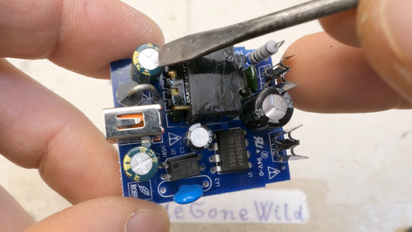
The sad state of plug-in USB power supplies is one of [DiodeGoneWild]’s pet gripes, and deservedly so. Most USB chargers cram a lot of electronics into a mighty small volume, and are built to a price point, meaning that something has to give in the design. In the case of the two units he tears apart in the video below, it’s pretty clear where the compromises are. Neither unit met the specs on the label in terms of current supplied and voltage regulation, even the apparently more capable quick charger, which is the first to go under the knife. The PCB within holds some alarming surprises, like the minimal physical isolation between the mains part of the circuit and the low-voltage section, but the real treat is the Schottky diode that gets up to 170°C under full load. Safety tip: when you smell plastic burning, throw the thing out.

The second charger didn’t fare any better; although it didn’t overheat, that’s mainly because it shut itself off before it could deliver a fraction of its rated 1 amp output. The PCB construction was shoddy in the extreme, with a squiggly trace standing in for a proper fuse and a fraction of a millimeter separation between primary and secondary traces. The flyback transformer was a treat, too; who doesn’t want to rely on a whisper-thin layer of cheap lacquer to keep mains voltage out of your phone?

All in all, these designs are horrible, and we have to thank [DiodeGoneWild] for the nightmares we’ll have whenever we plug into one of these things from now on. On the other hand, this was a great introduction to switch-mode power supply designs, and what not to do with our own builds. Continue reading “Just How Dodgy Are Cheap USB Chargers Anyway?”

Laptop USB-C Charging Hack Lets You Leave The Brick At Home

At their best, laptops are a compromise design. Manufacturers go to great lengths to make the slimmest, lightest, whatever-est laptops possible, and the engineering that goes into doing so is truly amazing. But then they throw in the charger, which ends up being a huge brick with wire attached to it, and call it a day.

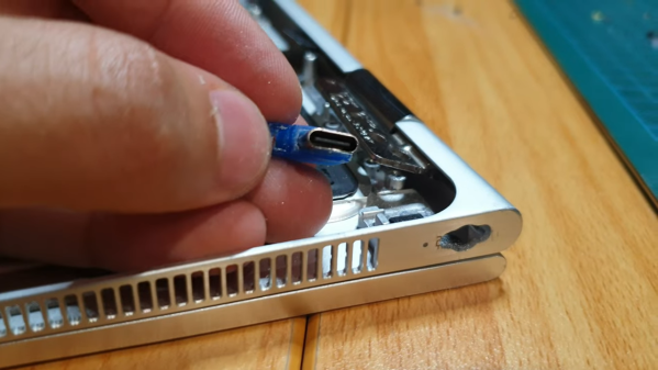
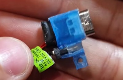
Does it have to be that way? Probably, but that doesn’t mean we can’t try to slim down the overall footprint of laptops at least a little. That’s what [Joe Gaz] did when he hacked his laptop to allow for USB-C charging. Tired of the charger anchoring down his HP X360, [Joe] realized that he could harvest the PCB from a USB-C charger adapter dongle and embed it inside his laptop. We’ve seen similar modifications made to Thinkpads in the past, and it’s good to see the process isn’t that far removed with other brands.

After popping open the laptop, which is always an adventure in reverse mechanical engineering, he found that removing the OEM charger jack left just enough room for the USB-C charger. Mounting the board required a 3D printed bracket, while enlarging the original hole in the side of the laptop case took some cringe-inducing work with a file. It looked like it was going to be pretty sloppy at first, but he ended up doing a pretty neat job in the end. The whole modification process is in the video below.

The end result is pretty slick — [Joe] can now carry a much more compact USB wall-wart-style charger, or eschew the charger altogether and rely on public USB charging stations. Either way, it sure beats lugging a brick around. If you’re interested in laptop hacking, or even if you just want to harvest the goodies from a defunct machine, check out this guide to laptop anatomy by our own [Arsenijs Picugins].

Continue reading “Laptop USB-C Charging Hack Lets You Leave The Brick At Home”

DIY SSR For Mains Switching

Typical power strips have their sockets tightly spaced. This makes it cumbersome to connect devices whose wall warts or power bricks are bulky — you end up losing an adjoining socket or two. And if the strip has a single power switch, you cannot turn off individual devices without unplugging them.

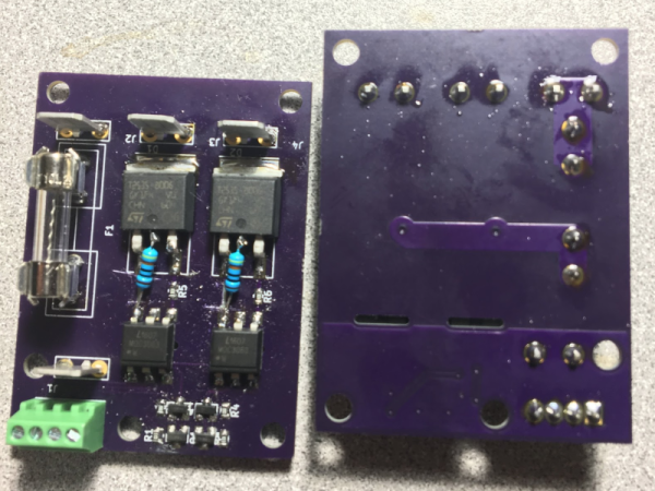
Planning to tackle both problems together, [Travis Hein] built himself some custom Dual SSR Controlled Socket Outlets for his workbench. He also decided to add remote switching ability so he could turn off individual sockets via a controller, Raspberry Pi, smartphone app or most ideally, a nice control panel on his desk consisting of a bank of switches.

The easiest solution for his problem would have been to just buy some off-the-shelf SSR or relay modules and wire them up inside his sockets. But he couldn’t find any with the features he wanted, and SSR’s were a little bit on the expensive side. Also, we wouldn’t have a project to write about – sometimes even the simple ones can show us a thing or two.

For starters, he walks us through a quick and simplified primer on figuring out thermal dissipation for the triacs which will be used on his boards. This is tricky since the devices are connected directly to utility voltage so he needs to take care of track clearances, mechanical separation as well as safety. However, for his first board prototypes, he did not add any heat sinking for the triacs, thereby limiting their use to low current loads. Since the SSR also needs to have a wide control voltage range, he describes how the two transistor constant-current input block works to limit opto-triac LED current over a range of 2 V to 30 V.

Before he moves on to his next prototype, [Travis] is looking for feedback to improve his design, make it safer, and figure out if it can pass safety protocols. Let him know via comments below.

USB Charger Fooled Into Variable Voltage Source

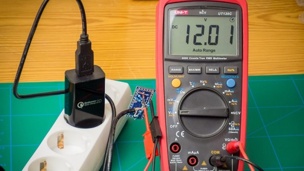
USB chargers are everywhere and it is the responsibility of every hacker to use this commonly available device to its peak potential. [Septillion] and [Hugatry] have come up with a hack to manipulate a USB charger into becoming a variable voltage source. Their project QC2Control works with chargers that employ Quick Charge 2.0 technology which includes wall warts as well as power banks.

Qualcomm’s Quick Charge is designed to deliver up to 24 watts over a micro USB connector so as to reduce the charging time of compatible devices. It requires both the charger as well as the end device to have compatible power management chips so that they may negotiate voltage limiting cycles.

In their project, [Septillion] and [Hugatry] use a 3.3 V Arduino Pro Mini to talk to the charger in question through a small circuit consisting of a few resistors and diodes. The QC2.0 device outputs voltages of 5 V, 9 V and 12 V when it sees predefined voltage levels transmitted over the D+ and D- lines, set by Arduino and voltage dividers. The code provides function calls to simplify the control of the power supply. The video below shows the hack in action.

Quick Charge has been around for a while and you can dig into the details of the inner workings as well as the design of a compatible power supply from reference designs for the TPS61088 (PDF). The patent (PDF) for the Quick Charge technology has a lot more detail for the curious.

Similar techniques have been used in the past and will prove useful for someone looking for a configurable power supply on the move. This is one for the MacGyver fans.

Continue reading “USB Charger Fooled Into Variable Voltage Source”

Scope Noob: Probing Alternating Current

I finally did it. After years of wanting one (and pushing off projects because I didn’t have one) I finally bought an oscilloscope. Over the years I read and watched a ton of content about how to use a scope, you’d think I would know what I’m doing. Turns out that, like anything, hands-on time with an oscilloscope quickly highlighted the gaping holes in my knowledge. And so we begin this recurring column called Scope Noob. Each installment will focus on a different oscilloscope-related topic. This week it’s measuring a test signal and probing Alternating Current.

Measuring a Signal
test-signal

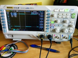
Hey, measuring signals is what oscilloscopes are all about, right? My very first measurement was, of course, the calibration signal built into the scope. As [Chris Meyer] at Sector67 hackerspace here in Madison put it, you want to make sure you can probe a known signal before venturing into the unknown.

In this case I’m using channel 2. Everything on this scope is color-coded, so the CH2 probe has blue rings on it, the probe jack has a blue channel label, and the trace drawn on the screen is seen in blue. I’m off to a fantastic start!

This scope, a Rigol 1054z, comes with an “auto” button which will detect the signal and adjust the divisions so that the waveform is centered on the display. To me this feels like a shortcut so I made sure to do all of this manually. I started with the “trigger” which is a voltage threshold at which the signal will be displayed on the screen. The menu button brings up options that will let you choose which channel to use as trigger. From there it was just a matter of adjusting the horizontal and vertical resolution and position before using the “cursor” function to measure the wave’s voltage and time.

I played around with the scope a bit more, measuring some PWM signals from a microcontroller. But you want to branch out. Because I don’t have a proper signal generator, the next logical thing to measure is alternating current in my home’s electrical system. I suppose you could call it a built-in sine wave source.

Probing Alternating Current
acac-wall-wart

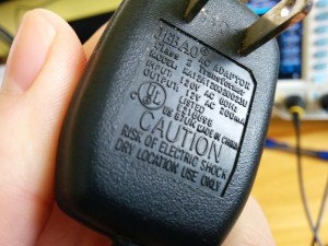
I sometimes take criticism for never throwing things away. Seven years ago we had a cat water fountain whose motor seized. It was powered by a 12V AC to AC converter seen here. Yep, I kept it and was somehow able to find it again for this project.

Of course at the time I thought I would build a clock that measures mains frequency to keep accurate time. This would have done the trick had I followed through. But for now I’m using it to protect me (and my fancy new scope) from accidental shock. I’ll still get the sine wave I’m looking for but with a source that is only 12V at 200 milliamps.

Don’t measure mains directly unless you have a good reason to do so.

Continuing on my adventure I plugged in the wall wart and connected the probe to one of the two wires coming out of it. But wait, what do I do with the probe’s reference clip? I know enough about home electrical to know that one prong of the plug is hot, the other is neutral. The clip itself is basically connected directly to mains ground. Bringing the two together sounds like a really bad idea.

This turns out to be a special case for oscilloscopes, and one that prompted me to think about writing this column. Had this been a 3-prong wall wart, connecting the probe’s reference clip to one of the wires would have been a very bad thing. Many 3-prong wall warts reference the mains earth ground on one of the outputs. If that were the case you could simply leave the clip unconnected as the chassis ground of your scope is already connected to mains ground via its own 3-prong power cord and the reference clip is a dead short to that. If you did need to probe AC using the reference clip you need an isolation transformer for your scope. There are bigger implications when probing a board powered from mains which [Dave Jones] does an excellent job of explaining. Make sure you check out his aptly named video: How NOT to blow up your oscilloscope.

As I understand it, and I hope you’ll weigh in with a comment below, since the wall wart I’m using has a transformer and no ground plug I’m fine using the ground clip of the probe in this case. Even though I’m clipping it to an AC line, the transformer prevents any kind of short between hot/neutral mains and earth ground (via the probe’s ground clip). What I don’t understand is why it’s okay to connect the transformed side of the 12V AC to mains ground?

At any rate, the screenshots above show my progress through this measurement. I first connected the probe without the ground clip and got the sad-looking trace seen on the left. After conferring with both [Adam Fabio] and [Bil Herd] (who had differing opinions on whether or not I should “float the scope”) I connected the ground clip and was greeted with a beautifully formed sine wave. I’m calling this a success and putting a notch in the old bench to remember it by.

What’s Next?
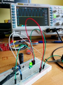
bridge-recctifier-teaserI don’t want to get too crazy with the first installment of Scope Noob so I’ll be ending here for now. I need your guidance for future installments. What interesting quirks of an oscilloscope should a noob like me explore? What are your own questions about scope use? Leave those below and we’ll try to add them to the lineup in the coming weeks.

Homework

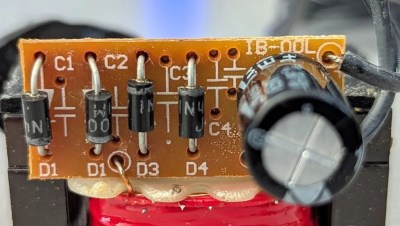
For next week I’m working my way through the adventure of rectifying this 12V AC signal into a smoothed DC source. Here you see a teaser of those experiments. I’ve built a full-wave rectifier using just four diodes (1N4001) and will plunk in a hugely-over-spec’d electrolytic capacitor to do the smoothing. If you want to follow along on the adventure you should dig around your parts drawers for these components and give it a try yourself this week. We’ll compare notes in the next post!
Dummy Batteries Let You Use An AC Adapter

We find it frustrating when battery operated consumer electronics don’t include a way to connect an external power supply. We try not to purchase disposable alkaline cells if we can avoid it, and this dummy battery AC adapter hack will aid in our mission.

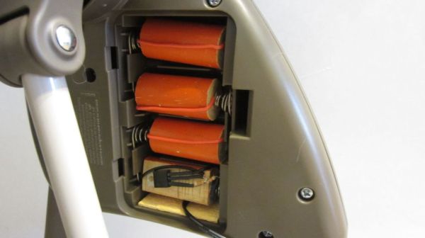
The battery compartment shown above is for a motorized baby swing. It accepts C sized batteries (who has those just lying around?) and lacks a barrel jack to connect a wall wart adapter. [Jason Smith] mentions you can get around this by connecting your positive and ground wires directly to the conductor springs. But using a dummy battery makes it a bit easier to remove the adapter if you do want to use battery power.

Each of the orange dummy is a wooden dowel with a screw at each end. The screws are connected with a piece of jumper wire, shorting the two terminals. This completes the circuit in the battery compartment and allows him to power everything from the adapter cell at the bottom. The adapter uses an LM317 adjustable voltage linear regulator. He used fixed resistor values to dial in his target voltage. The equipment should be rather forgiving as battery voltage starts higher than the printed value and drops as the cells are used up.

This technique has been around for a long time. One of our favorites was a hack that converted an Apple Magic Trackpad to USB power.

Continue reading “Dummy Batteries Let You Use An AC Adapter”

Wall Wart Computer Mouse

SAMSUNG

This rather bulky looking wall wart is actually a computer mouse. Sure, it may cause your hand to cramp horribly if used for any length of time. But some would say it’s worth that for the hipster value of the thing.

The rather odd shape is somewhat explained by the fact that this was sourced from Ikea. After gutting the transformer found inside the plastic case he had plenty of room to work with. He drilled a hole so that the sensor from a Logitech USB optical mouse can pick up the movement of the mouse. He also got pretty creative when it came to the buttons. The two prongs of the wall plug pivot horizontally to affect the momentary press switches inside.

After the break you can see a quick demo of the project. [Alec] doesn’t consider it to be complete. He wants to make a couple of improvements which include adding weight to make it feel more like the original wall wart, and finding a way to hide the hole he drilled for the sensor.

Continue reading “Wall Wart Computer Mouse”