PS3 Controller

Get Better At Mortal Kombat By Hacking Your PS3 Controller

Fighting games like Mortal Kombat provide you with a variety of different available moves. These include kicks, punches, grabs, etc. They also normally include various combination moves you can perform. These combo moves require you to press the proper buttons in the correct order and also require you to time the presses correctly. [Egzola] realized that he could just hack his controller to simulate the button presses for him. This bypasses the learning curve and allows him to perform more complicated combinations with just the press of a single button.

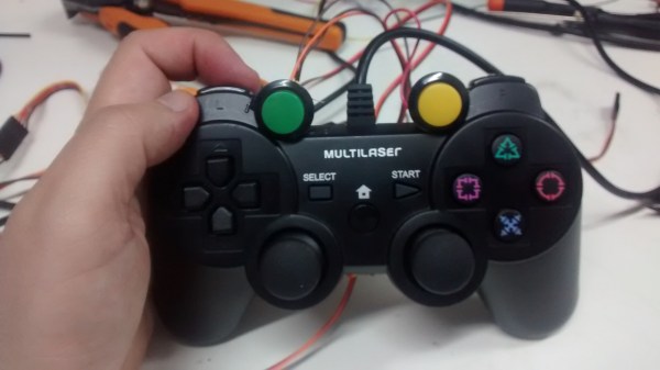
[Egzola] started by taking apart his Playstation 3 controller. There were two PCB’s inside connected by a ribbon cable. Luckily, each individual pad for this cable was labeled with the corresponding controller button. This made it extremely simple to hack the controller. [Egzola] soldered his own wires to each of these pads. Each wire is a different color. The wires then go to two different connectors to make them easier to hook up to a bread board.

Each wire is then broken out on the breadboard. The signal from each button is run through a 4n25 optoisolator. From there the signal makes its way back to various Arduino pins. The 4n25 chips keeps the controller circuit isolated from the Arduino’s electrical circuit. The Arduino also has two push buttons connected to it. These buttons are mounted to the PS3 controller.

Now when [Egzola] presses one of the buttons, the Arduino senses the button press and simulates pressing the various controller buttons in a pre-programmed order. The result is a devastating combination move that would normally require practice and repetition to remember. You might say that [Egzola] could have spent his time just learning the moves, but that wasn’t really the point was it? Check out the video below for a demonstration. Continue reading “Get Better At Mortal Kombat By Hacking Your PS3 Controller”

Automatic Closet Lightswitch

closet-door-switch-box

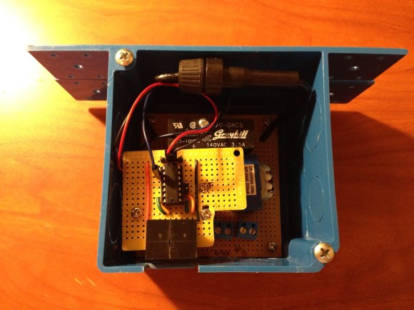
[Dillon] wrote in to tell us about his latest project, an automatic light switch for a the hallway closet in his house. Although this project could probably be done very simply, [Dillon] accomplished everything in a way that actually looks professionally done and has some neat features. Check out his site for more pictures of the build.

Not that we at [HAD] mind a bit of messy wiring, but if it’s going inside a house, neater is always better. On the other hand, this project took nearly a year to go from idea to implementation, so please keep submitting your spaghetti-wired projects.  We understand.

As an electrical engineering major, [Dillon] didn’t skimp on basic electrical components, and has schematics available on his site. A MSP430 microcontroller provides the “brains” for everything, turning the light off after 5 minutes if the doors are not shut. Be sure to check out his video overview after the break with footage of it in action. Continue reading “Automatic Closet Lightswitch”

Stellarino Brings Wiring-style Coding To The Stellaris Launchpad

wiring-for-stellaris-launchpad

[Sultan Qasim] wrote in to tell us about the work he’s been doing on the Stellarino library. It’s goal is to break down the coding barriers present for those looking to move from Arduino to ARM. This is accomplished by facilitating Wiring-stlye code for the Stellaris Launchpad ARM development board.

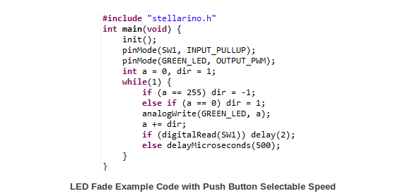
Right off the bat [Sultan] mentions that the interface is Wiring-like, but is not compatible with it. This means you can’t just plop your existing sketches into a C file and get them to work with the addition of a simple include file. But what it does do is provide access to the functions to which seasoned Arduino users have grown accustomed. You can see some examples above, including analogWrite(), digitalRead(), and a simple delay function.

We had a quick look at the library. It uses StellarisWare components which are stored in the ROM of the chip (these are all preceded by ‘ROM_’). The one thing missing is the UARTstudio library which apparently carries a license incompatible with GPL.

OmniDirectional Research Platform

[youtube=http://www.youtube.com/watch?v=-bcoAqKhdL4]

[Shachar Geiger] sent in an interesting project that he worked on with [Tal Avivi] at the Bezalel academy in Jerusalem. They were given the task of designing a 1-person electrical urban vehicle. They took some cues from MIT’s Transology and designed the OmniDirectional Research Platform (ODRi). There’s a video of it embedded above. It can be driven using three different input styles: an accelerometer joystick, a traditional gamepad, or body mass shift. They started with an Arduino, but needed more I/O and had to switch to a Wiring board (this was before the Mega). The platform is built mostly from scrap. The accelerometers were placed in an old Microsoft Sidwinder. The standard joystick is from a Sega Mega Drive. The weight sensors are out of cheap home scales.

Capacitance Sensor Guide (AD7746)

capacitive_sensor

[Marcus] has written up his experiences using the AD7746 capacitance sensor. He used the SparkFun breakout board in conjunction with an Arduino. The available Arduino code wasn’t that great so he rewrote it to be easier to understand. The AD7746 is an I2C device that can be continuously read, but this doesn’t mesh well with the Wiring libraries. Additionally, the calibration routine from the data sheet is difficult to understand. He’s included all of the code he used plus a Processing sketch to help visualize the input which will hopefully make your experience with the chip much more smooth.

ATmega Controller Wiring Upgrade

avrcontroller

[jelengar] liked the ease of use of the Arduino, but wanted a much higher pin count. He set about converting the ATmega Controller for use with Wiring, the code that the Arduino IDE is based on. The ATmega128 in the controller features 53 pins as opposed to the 11 on the Arduino’s ATmega168. You also get 128kb of memory. The process is fairly simple; you just need to add the appropriate crystal. You can also add a switch to trigger the bootloader and a status LED.

VU Meter Made With An LM3915


So here’s the situation: you have an audio device, maybe a boombox, perhaps one you built yourself, but it has no VU meter. No problem; building a VU meter is easy with these instructions from [Joe].

You’ll need either an LM3915 or LM3916 chip, a couple of bread boards, two audio jacks, ten LEDs, and a few other components. Wire them all together per the schematic, then plug an audio source into the input jack. You can plug your speakers or output device into the output jack, and you’re done. Keep in mind that LM3916s switch negative, so positive to positive wiring from LEDs to the bread board will be necessary. The wiring on [Joe]’s version is a bit convoluted, but it can be cleaned up on yours if you take the time. Video embedded below.

Continue reading “VU Meter Made With An LM3915”