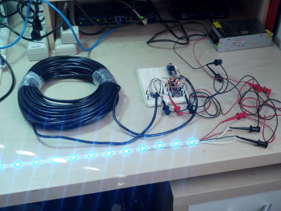
It seems like every third project on Hackaday uses WS2812 RGB LEDs in some way. We all love our blinkenlights, and bright, cheap, serial controlled RGB LEDs are the bees knees.
As with all products these days, competing manufacturers have discovered the huge market for these things, and clones are now available. [Tim] recently took a look at the PD9823, as well as three versions of the WS2812. [Tim] is considered something of a WS2812 guru here at Hackaday. You might remember him from his WS2812 driver optimization article, which should be required reading for any WS2812 hacker.
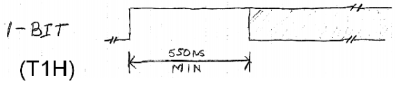
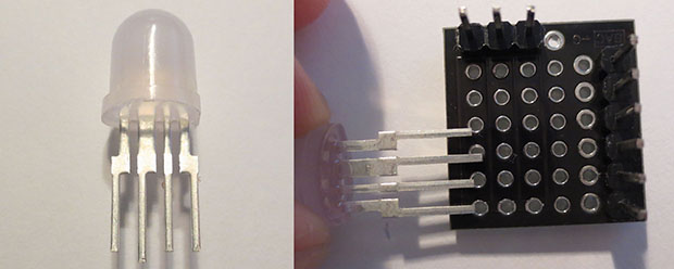
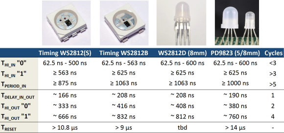
As many of us know, the timing characteristics for these LEDs can be a pain to work with. The values also differ between the WS2812S and WS2812B. [Tim] discovered that the new through hole WS2812D parts are different yet again, though rather close to the B parts. The PD9823’s designers must have studied the WS2812’s closely, as their 190ns time base falls directly between WS2812S 166ns time and the 208ns time of the WS2812B. The PD9823 also requires a slightly longer reset pulse.
The takeaway is that well written drivers such as [Tim’s] should have no problem with the new parts, but compatibility is something to keep in mind as more clones hit the market.