Showing pulse oximeter and color sensor combining to measure oxygen in blood and skin tone

Perfecting The Pulse Oximeter

We’re always looking for interesting biohacks here on Hackaday, and this new research article describing a calibrated pulse oximeter for different skin tones really caught our attention.

Pulse oximeters are handy little instruments that measure your blood oxygen saturation using photoplethysmography (PPG) and are a topic we’re no strangers to here at Hackaday. Given PPG is an optical technique, it stands to reason that its accuracy could be significantly affected by skin tone and that has been a major topic of discussion recently in the medical field. Given the noted issues with pulse oximeter accuracy, these researchers endeavored to create a better pulse oximeter by quantifying skin pigmentation and using that data to offset errors in the pulse oximeter measurements. A slick idea, but we think their results leave a lot to be desired.

Diagram showing pulse oximeter and color sensor combining to measure oxygen in blood and skin tone
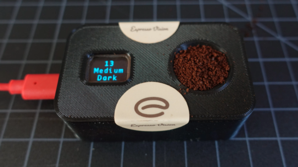
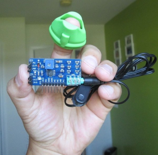
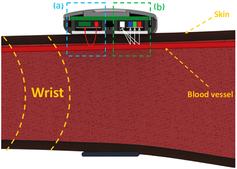
Their idea sounds pretty straightforward enough. They created their own hardware to measure blood oxygen saturation, a smartwatch that includes red and infrared (IR) light-emitting diodes (LED) to illuminate the tissue just below the surface of the skin, and a photosensor for measuring the amount of light that reflects off the skin. But in addition to the standard pulse oximeter hardware, they also include a TCS34725 color sensor to quantify the user’s skin tone.

So what’s the issue? Well, the researchers mentioned calibrating their color sensor to a standard commercially-available dermatology instrument just to make sure their skin pigmentation values match a gold standard, but we can’t find that data, making it a bit hard to evaluate how accurate their color sensor actually is. That’s pretty crucial to their entire premise. And ultimately, their corrected blood oxygen values don’t really seem terribly promising either. For one individual, they reduced their error from 5.44% to 0.82% which seems great! But for another user, their error actually increases from 0.99% to 6.41%. Not so great. Is the problem in their color sensor calibration? Could be.

We know from personal experience that pulse oximeters are hard, so we applaud their efforts in tackling a major problem. Maybe the Hackaday community could help them out?

Pulse Oximetry Sensor Judges Your Coffee Roast

Breakout board for the MAX30101, which [Zach] used as the basis of his roast gauge. The sensor is at the top edge of the board.
Parts designed and marketed for a specific application can nevertheless still be useful in other ways, and whenever that happens, it’s probably the start of a pretty good hack. Using a sensor for something other than its intended purpose is exactly what [Zach Halvorson] did to make the Roast Vision device, which uses the MAX30101, a sealed optical sensor intended mainly for pulse oximetry and heart-rate monitoring.

[Zach] is instead using that sensor to measure the roast level of coffee beans, and assign a consistent number from 0 to 35 to represent everything from Very Dark to Very Light. Measuring a bean’s roast level is important to any roaster seeking accuracy and consistency, but when [Zach] found that commercial roast gauges could easily cost over a thousand dollars, he was sure he could do better.

[Zach] settled on using a Sparkfun MAX30101 breakout board to develop his device, and Sparkfun shared an informative blog post that demonstrates how making hardware and tools more accessible can help innovative ideas flourish. The Roast Vision device has a 3D printed enclosure, and a simple top-loading design with an integrated sample cup makes it easy to use. One simply puts about a teaspoon of finely-ground coffee into the sample cup, and the unit provides a measurement in a couple of seconds. Fortunately the sensor works just fine though an acrylic window which means the device can be sealed; a handy feature for a tool that will spend a lot of time around ground coffee.

The joys of fresh roasted coffee is something that is perfectly accessible to those making small batches at home. There are commercial options for small roasters of course, but should you wish to go the DIY route, check out our own Elliot Williams’ guide on making a low-cost DIY roaster.

A Pulse Oximeter From Very Little

Against the backdrop of a global respiratory virus pandemic, it’s likely that more than a few readers have been thinking about pulse oximeters. You may even have looked at one closely and seen that it’s little more than a device which shines light through your finger, and wondered how they work. It’s something [Giulio Pons] has done, and to show us how it’s done he’s created a working pulse oximeter of his own.

He started with an infra-red heartbeat sensor module, which is revealed as nothing more than an IR LED and a photodiode. Sampling the output from the photodiode allows measurement of heartbeat, but gives not clue as to oxygen saturation. The interesting part comes via the property of red light in that it’s transmission through flesh varies with oxygen saturation, so adding a red LED and alternately measuring from the IR and red illuminations allows a saturation figure to be derived.

Commercial pulse oximeters are pretty cheap, so many of us will no doubt simply order one from the usual sources and call it good. But it’s always interesting to know how any device works, and this project reveals something simpler than we might have expected. If pulse oximeters interest you, compare it with this one we featured a few years ago.

Pulse Oximeter Is A Lot Of Work

These days we are a little spoiled. There are many sensors you can grab, hook up to your favorite microcontroller, load up some simple library code, and you are in business. When [Raivis] got a MAX30100 pulse oximeter breakout board, he thought it would go like that. It didn’t. He found it takes a lot of processing to get useful results out of the device. Lucky for us he wrote it all down with Arduino code to match.

A pulse oximeter measures both your pulse and the oxygen saturation in your blood. You’ve probably had one of these on your finger or earlobe at the doctor’s office or a hospital. Traditionally, they consist of a red LED and an IR LED. A detector measures how much of each light makes it through and the ratio of those two quantities relates to the amount of oxygen in your blood. We can’t imagine how [Karl Matthes] came up with using red and green light back in 1935, and how [Takuo Aoyagi] (who, along with [Michio Kishi]) figured out the IR and red light part.

The MAX30100 manages to alternate the two LEDs, regulate their brightness, filter line noise out of the readings, and some other tasks. It stores the data in a buffer. The trick is: how do you interpret that buffer? Continue reading “Pulse Oximeter Is A Lot Of Work”

Hackaday Prize Entry: Open-source Pulse Oximetry

Chances are pretty good you’ve had a glowing probe clipped to your fingertip or earlobe in some clinic or doctor’s office. If you have, then you’re familiar with pulse oximetry, a cheap and non-invasive test that’s intended to measure how much oxygen your blood is carrying, with the bonus of an accurate count of your pulse rate. You can run down to the local drug store or big box and get a fingertip pulse oximeter for about $25USD, but if you want to learn more about photoplethysmography (PPG), [Rajendra Bhatt]’s open-source pulse oximeter might be a better choice.

PPG is based on the fact that oxygenated and deoxygenated hemoglobin have different optical characteristics. A simple probe with an LED floods your fingertip with IR light, and a photodiode reads the amount of light reflected by the hemoglobin. [Rajendra]’s Easy Pulse Plugin receives and amplifies the signal from the probe and sends it to a header, suitable for Arduino consumption. What you do with the signal from there is up to you – light an LED in time with your heartbeat, plot oxygen saturation as a function of time, or drive a display to show the current pulse and saturation.

We’ve seen some pretty slick DIY pulse oximeters before, and some with a decidedly home-brew feel, but this seems like a good balance between sophisticated design and open source hackability. And don’t forget that IR LEDs can be used for other non-invasive diagnostics too.

The 2015 Hackaday Prize is sponsored by:

Pulse Oximeter From LM324, LED, And Photodiode

This pulse oximeter is so simple and cheap to build it’s almost criminal. The most obvious way to monitor the output of the sensor is to use an oscilloscope. The poor-man’s stand-in for that is a sound card, which is what [Scott Harden] demonstrates in his write-up.

It uses a concept we’ve seen a few times before. The light from an LED shines through your finger and is measured on the other side by a phototransistor. It’s that light grey plastic thing you see on a patient’s finger when they’re in the hospital. [Scott] went with a common wooden clothes pin as a way to mount and align the sensor with your finger. It is monitored by the simplest of circuits which uses just one chip: an LM324 op-amp. There are three basic stages which he explains well in the video after the jump. The incoming signal is decoupled before being fed to the first amplifier stage. From there it is fed to an adjustable low-pass filter to help eliminate 60Hz noise from AC power in the room. The last stage amplifies the signal again while using another low-pass filter in parallel.

Continue reading “Pulse Oximeter From LM324, LED, And Photodiode”

Pulse Oximeter Displays Blood Oxygen Levels On A PC

The last time you were in the emergency room after a horrible accident involving a PVC pressure vessel, a nurse probably clipped a device called a pulse oximeter onto one of your remaining fingers. These small electronic devices detect both your pulse and blood oxygen level with a pair of LEDs and a photosensor. [Anders] sent in a great tutorial for building your own pulse oximeter using a fancy ARM dev board, but the theory behind the operation of this device can be transferred to just about any microcontroller platform.

The theory behind a pulse oximeter relies on the fact that hemoglobin absorbs red and infrared light differently based on its oxygenation levels. By shining a red and IR LED through a finger onto a photoresistor, it’s possible to determine a person’s blood oxygen level with just a tiny bit of math.

Of course a little bit of hardware needs to be thrown into the project; for this, [Anders] used an EMF32 Gecko starter kit, a great looking ARM dev board. After connecting the LEDs to a few transistors and opamps, [Anders] connected his sensor circuit to the ADC on the Gecko board. From here it was very easy to calculate his blood oxygen level and even display his pulse rate to a PC application.

Yes, for just the price of a dev board and a few LEDs, it’s possible to build your own medical device at a price far below what a commercial pulseox meter would cost. FDA approval not included.