We’ve all experienced power outages of some kind, be it a breaker tripping at an inconvenient time to a storm causing a lack of separation between a tree and a power line. The impact is generally localized and rarely is there a loss of life, though it can happen. But in the video below the break, [Grady] of Practical Engineering breaks down the Northeast Blackout of 2003, the largest power failure ever experienced in North America. Power was out for days in some cases, and almost 100 deaths were attributed to the loss of electricity.
[Grady] goes into a good amount of detail regarding the monitoring systems, software simulation, and contingency planning that goes into operating a large scale power grid. The video explains how inductive loads cause reactance and how the effect exacerbated an already complex problem. Don’t know what inductive loads and reactance are? That’s okay, the video explains it quite well, and it gives an excellent basis for understanding AC electronics and even RF electronic theories surrounding inductance, capacitance, and reactance.
So, what caused the actual outage? The complex cascade failure is explained step by step, and the video is certainly worth the watch, even if you’re already familiar with the event.
It would be irresponsible to bring up the 2003 outage without talking about the Texas ERCOT outages just one year ago– an article whose comments section nearly caused a blackout at the Hackaday Data Center!
The circuit is a simple one, and a classic. The spring from a ballpoint pen is soldered to the base of a BC547 transistor, and when held close enough to a conductor carrying AC power, a current is induced in the spring which is sufficient to turn the transistor on. The transistor then switches on a second BC547, which lights an LED. The whole circuit is built on top of a battery clip so it can be run straight from the top of a standard 9 volt battery.
It’s a circuit you’ll find all over the place, even built into many modern multimeters. It can be particularly useful to help avoid drilling through mains wires embedded in the walls of your home. Of course, if you’d like even more information about what’s lurking within your walls, consider this capacitive imaging hack. Video after the break.
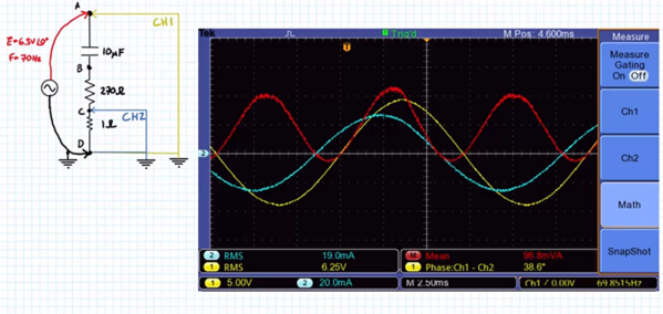
If you want to measure voltage you reach for a voltmeter. Current? An ammeter. Resistance? An ohmmeter. But what about measuring AC power? A watt meter? Usually. But if you know what to do, you could also reach for your oscilloscope. If you don’t know what to do, [Jim Pytel] has the video answers for you. Truth is, an oscilloscope can measure almost anything if you know how. [Jim] shows how to measure the voltage and current in a circuit and then it is simply a matter of doing a little math, something modern scopes can do very easily.
We like that [Jim] shows a circuit and how the math works before he verifies the math with the scope. Of course, theory doesn’t always match practice. The method uses a small current-sensing resistor that throws readings off a bit. The scope and signal generator are not perfect, either. However, the results match up pretty nicely with the computed results.
You might be reading this six minutes early. Assuming that the Hackaday editors have done their job, this article should have appeared in your feed right on the half-hour. We have a set schedule to keep you supplied with the tastiest of hardware hacks and news. For some of you though perhaps there has been a treat, you’ve seen it and all the other stories six minutes early.
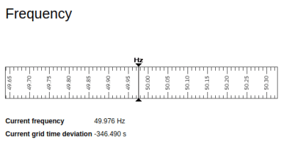
Think for a minute of a modern car on a hot day. When you turn on the air conditioning you will hear a slight dip in the engine revs as it accommodates the extra load. So it is with an alternating current power grid; a simple example is a power station supplying a city. In periods such as cold nights when the demands of the city go up, the result would be that the power station needs to work harder to satisfy it, and until that happens there would be a slight dip in its line frequency. Power grids compensate for this by increasing and decreasing the available generating capacity in real time, maintaining a mean frequency such that the “grid time” of a clock controlled by it matches an atomic clock as closely as possible over time.
It is at this point we leave the realm of electrical engineering and enter that of international politics, normally something far removed from Hackaday’s remit. It is fair to say that the history between Serbia and Kosovo is extremely delicate, and to understand some of the context of this story you should read about the war at the end of the 1990s. After the conflict the Serbian-majority region of what is now Kosovo refused to pay the Kosovan utility for its electricity, eventually leading to the Kosovans refusing to pay for that region’s share of the power received by Kosovo from Serbia. The resulting imbalance between demand and supply was enough to drag the supply frequency down across the whole continent, and though a short-term agreement has been reached the problem still remains on the grid.
Clocks and Mains Frequency
So if you are a continental European and you find yourself six minutes behind your British or American friends, don’t worry. We know that among our readers are people with significant experience in the power generation world, perhaps some of you would like to use your six minutes to give us a bit of insight in the comments. Meanwhile here at Hackaday we maintain an interest in the mechanics of power distribution even if some might say that it is Not A Hack. We’ve taken a look at utility poles, and examined how power grids are synchronised.
As for those slow clocks, the use of mains frequency to keep accurate time is quite brilliant and has been used reliably for decades. Tightly regulating grid frequency means that any clock plugged into an outlet can have the same dead-on accuracy for the cost of a few diodes. These clocks count the zero crossing of the alternating current. There may be moment to moment drifts but the power utility injects or removes cycles over the long term so the sum of crossings is dead on over the course of the day. It’s an interesting phenomenon to experiment with and that’s why we see it in microcontroller projects from time to time.
Low power devices are always intriguing, as they open up possibilities for applications with the need to operate remotely, or for very long periods without attention. There are all manner of techniques for powering such devices, too, such as using solar panels, super capacitors, or other fancy devices. The Micro Power Snitch is one such device, which can report wirelessly on your AC-powered appliances.
The device is built around a tiny ARM microcontroller and an RFM69 radio module. The entire circuit is run by leeching power from an AC current transformer, wrapped around one of the power lines of an AC appliance. When an appliance draws over the minimum threshold current (500W on 230VAC, 250W on 115VAC), the device sends a packet out, which can be received and logged at the other end.
The best part of this project, however, is the writeup. The project is split into an 8-part series, breaking down the minutiae of the concepts at work to make this possible. It’s a great primer if you’re interested in designing low-power devices.
There are probably times in every Hackaday reader’s life at which you see something and realise that the technology behind it is something you have always taken for granted but have never considered quite how it works. Where this is being written there was such a moment at the weekend, an acquaintance on an amateur radio field day posted a picture of three portable gas-powered alternators connected together and running in synchronization. In this case the alternators in question were fancy new ones with automatic electronic synchronization built-in, but it left the question: how do they do that? How do they connect a new power station to the grid, and bring it into synchronization with the line? There followed a casual web search, which in turn led to the video below the break of a bench-top demonstration.
If two AC sources are to be connected together to form a grid, they must match each other exactly in frequency, phase, and voltage. To not do so would be to risk excessive currents between the sources, which could damage them and the grid infrastructure. The video below from [BTCInstrumentation] demonstrates in the simplest form how the frequencies of two alternators can be matched, by measuring the frequency difference between them and adjusting their speed and thus frequency until they can be connected. In the video he uses neon bulbs which flash at the difference frequency between the two alternators, and demonstrates adjusting the speed of one until the bulbs are extinguished. The two alternators can then be connected, and will then act together to keep themselves in synchronization. There are further videos in which he shows us the same process using a strobe light, then demonstrates the alternators keeping themselves synchronized, and phase deviation between them.
Of course, utility employees probably do not spend their time gazing at flashing neon bulbs to sync their power stations. The same measurements are not performed by eye but by electromechanical or electronic systems with automatic control of the contactors, just as they are in the fancy electronic alternator mentioned earlier. But most of us have probably never had to think about synchronizing a set of alternators, so to see it demonstrated in such a simple manner should fill a knowledge gap even if it’s one only of idle curiosity.