Erasing EEPROMs Isn’t Always As Easy As It Seems

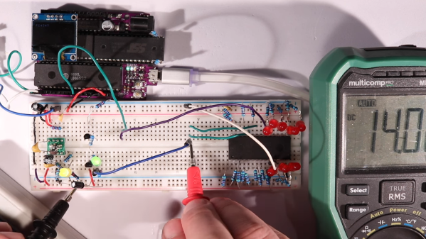
When is 14 volts not actually 14 volts? Given [Anders Nielsen]’s recent struggles with erasing an old-school EEPROM, it’s when you really need it that things tend to go pear-shaped.

A little background is perhaps in order. [Anders] is working on a scratch-built programmer for ROMs to complement his 65uino project, which puts a complete 6502 computer into the footprint of an Arduino Uno. He wisely started the ROM programmer project at the beginning, which was to generate the correct voltages for programming. This turned out to be not as easy as you might think thanks to the solderless breadboard’s parasitic effects on the MIC2288 switching boost regulator he chose.

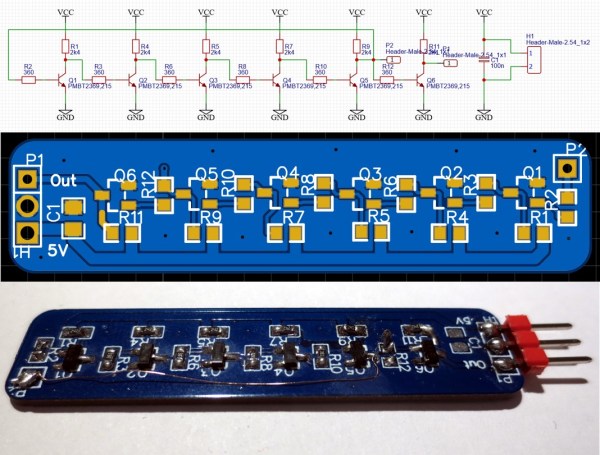
The video below is a continuation of the programmer build, which ends up being just as fraught as the first part. Being able to generate the programming voltages is one thing; getting them onto the right pins at the right time using nothing but the 5-volt GPIOs on a microcontroller is another. In true retro fashion, [Anders] tackled that problem with a pair of small-signal transistors, which seemed to work once the resistor values were sorted, at least when applying a 12-volt signal intended to show the ROM’s hard-coded manufacturer ID on the data bus.

But erasing the ROM, which requires 14 volts while the chip enable line is held high for 100 ms, proved a little trickier. Despite multiple tries, the ROM wouldn’t erase thanks to the 14-volt rail being dragged down to around 9 volts. [Anders] fixed that with a new base resistor on the driver, to increase the current and keep the voltage up where it needs to be. Just goes to show you that the data sheets don’t always tell the whole story.

We’ve been enjoying the unfolding story of this programmer, and we’re looking forward to the next installment.

Continue reading “Erasing EEPROMs Isn’t Always As Easy As It Seems”

The Geometry Of Transistors

Building things in a lab is easy, at least when compared to scaling up for mass production. That’s why there are so many articles about fusion being right around the corner, or battery technology that’ll allow aviation to switch away from fossil fuels, or any number of other miraculous solutions that never come into being. They simply don’t scale or can’t be manufactured in a cost effective way. But even when they are miraculous and can be produced on a massive scale, as is the case for things like transistors, there are some oddities that come up as a result of the process of making so many. This video goes into some of the intricacies of a bipolar junction transistor (BJT) and why it looks the way it does.

The BJT in this video is a fairly standard NPN type, with three layers of silicon acting as emitter, base, and collector. Typically when learning about electronics devices the drawings of them are simplified two-dimensional block diagrams, but under a microscope this transistor at first appears nothing like the models shown in the textbook. Instead it resembles more of a bird’s foot with a few small wires attached. The bird’s foot shape is a result of attempting to lower the undesirable resistances of the device and improve its performance, and some of its other quirks are due to the manufacturing process. That process starts with a much larger layer of doped silicon that will eventually become the collector, and then the other two, much smaller, layers of the transistor deposited on top of the collector. This also explains while it looks like there are only two layers upon first glance, and also shows that the horizontal diagram used to model the device is actually positioned vertically in the real world.

For most of the processes in our daily lives, the transistor has largely been abstracted away. We don’t have to think about them in a computer that much anymore, and unless work is being done on high-wattage power electronics devices, radios, or audio amplifiers it’s not likely that an average person will run into a transistor. But this video goes a long way to explaining the basics of one of the fundamental building blocks of the modern world for those willing to take a dive into the physics. Take a look at this video as well for an intuitive explanation of the close cousin of the BJT, the field-effect transistor.

Continue reading “The Geometry Of Transistors”

Sounding The Humble LED

Here at Hackaday we’re no strangers to the colorful glow of LEDs. But what if there was more to appreciate beneath the surface? Back in 2011 [Windell] over at Evil Mad Scientist dug into a certain variety of LED and discovered they had a song to sing.

Over the last couple decades, you’ve likely encountered the flickering “candle flame” variety of LED. Often found embedded in small plastic candle simulacra they are shaped like typical through hole “gumdrop” style LEDs, but pack some extra magic which causes them to flicker erratically. Coupled with a warm white color temperature the effect isn’t entirely dissimilar to the flickering of a candle flame.

To the Hackaday reader (and [Windell]) the cause of the flickering may be fairly clear, there is an IC embedded in the lens of the LED. See photo at top for an example of how this might look, helpfully magnified by the lens of the LED itself. Looking through the lens the captive die is visible, as well as the bond wires connecting it to the legs and light emitting diode itself. [Windell]’s observation is that together this assembly makes for a somewhat strange electrical component; from the perspective of the circuit it appears to randomly vary the current flowing through the LED.

He includes two interesting demos. One is that by attaching the flickering LED to a BJT he can turn it into a current amplifier and successfully drive a much more powerful 1W LED with the same effect. The other is that  with the power of the amplifier the same flickering LED can drive a buzzer as well. The effect is surprisingly pleasant, though we’d hesitate to call it musical.

For a more recent example of a similar phenomenon with a very different sound, check out out [Emily Velasco]’s playback of a similarly constructed RGB color changing LED, embedded below. We’ve seen optical tools used to decode LED flickers into data streams, but not for audio playback! We have also covered some LED flicker reverse engineering that spills more of the mystery sealed up in these specialized diodes.

Continue reading “Sounding The Humble LED”

The Descendants Of Ancient Computers

Building computers from discrete components is a fairly common hobby project, but it used to be the only way to build a computer until integrated circuits came on the scene. If you’re living in the modern times, however, you can get a computer like this running easily enough, but if you want to dive deep into high performance you’ll need to understand how those components work on a fundamental level.

[Tim] and [Yann] have been working on replicating circuitry found in the CDC6600, the first Cray supercomputer built in the 1960s. Part of what made this computer remarkable was its insane (for the time) clock speed of 10 MHz. This was achieved by using bipolar junction transistors (BJTs) that were capable of switching much more quickly than typical transistors, and by making sure that the support circuitry of resistors and capacitors were tuned to get everything working as efficiently as possible.

The duo found that not only are the BJTs used in the original Cray supercomputer long out of production, but the successors to those transistors are also out of production. Luckily they were able to find one that meets their needs, but it doesn’t seem like there is much demand for a BJT with these characteristics anymore.

[Tim] also posted an interesting discussion about some other methods of speeding up circuitry like this, namely by using reach-through capacitors and Baker clamps. It’s worth a read in its own right, but if you want to see some highlights be sure to check out this 16-bit computer built from individual transistors.

Switching: From Relays To Bipolar Junction Transistors

How many remote controls do you have in your home? Don’t you wish all these things were better integrated somehow, or that you could add remote control functionality to a random device? It’s a common starting point for a project, and a good learning experience for beginners.

A common solution we’ve seen applied is to connect a relay in parallel to all the buttons we want to press. When the relay is triggered, for example by your choice of microcontroller, it gets treated as a button press. While it does work, relays are not really the ideal solution for the very low current loads that we’re dealing with in these situations.

As it turns out, there are a few simple ways to solve this problem. In this article, we’re going to focus on using common bipolar junction transistors instead of relays to replace physical switches. In short, how to add transistors to existing electronics to control them in new ways.

Continue reading “Switching: From Relays To Bipolar Junction Transistors”

Breadboarding RAM

If you’ve ever wanted to dive in and take a look at how memory hardware is implemented here is a good example of how to implement some latching circuits with ether BJT or CMOS transistors. BJTs require biasing resistors which increases the complexity and power consumption when compared to CMOS. If power consumption isn’t an issue you could certainly make some really fast logic.

Most modern on chip RAM is made using SRAM because it only takes six transistors to implement(vs eight) and is pretty fast. When it comes to density DRAM can get one bit of storage by using a single transistor and capacitor(putting the capacitor underneath he transistor can save even more space). All that said, latches and flip flops are still a very useful (and common) tool when working with digital circuits.