Hackaday Prize 2023: 10 KW Electronic Load

[tinfever] needed a high-power benchtop electronic load for an upcoming project, and by their own admission decided foolishly to build their own. And we’re glad they did. The thing is, whilst this isn’t exactly a super-cheap project to build, buying a commercial offering with a capability of 10 kW and up to 30 kW pulsed, is going to cost an absolute fortune.

A selection of small resistors

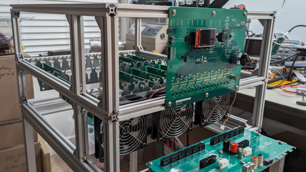
Built inside a cubic frame using what appears to be standard 2020 aluminum rails and fixturing, the modular construction is nice and clean, with plenty of space around the load boards to allow the cooling air to circulate.

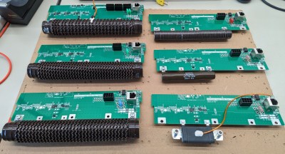
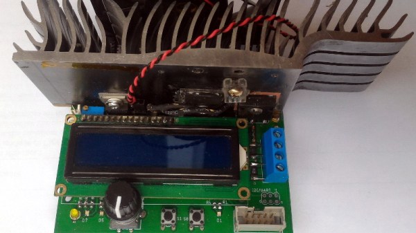
The operating principle is very simple; custom PCBs act in parallel to provide any load needed, by switching in the on-board load resistor. Each load board handles all the details of switching and dumping the power due to the inductance in the system wiring and the wire-wound resistors themselves.

Whilst we know that wire-wound resistors are reverse-wound to minimize inductance, there will still be some, and each load board will contribute a little more when the whole system is scaled up. Also, each load PCB handles its own temperature sensing, and current measurement passing these data off to the control PCB. A front-end connector PCB provides a variety of connection options to interface to the DUT (Device Under Test.) The system controller is based around an STM32 processor which deals with quite a lot more than you might think is needed on a first look.

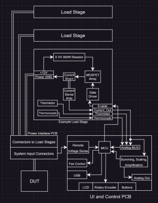
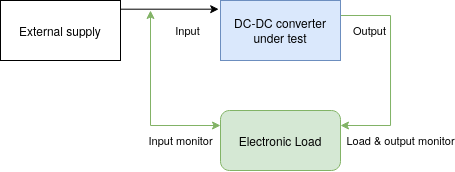
The sense currents from each load need to be sensed, scaled, and summed to keep the overall load accuracy within the 1% spec. Also, it is on duty for PWM control of the cooling fans, handling the user interface, and any other remote connectivity. There are a lot of details on the project page, as we’re only skimming the surface here. If you’re interested in building an active load, this is a project you really should be digging into.

We shall watch with interest for when [tinfever] scales up this eight-slot prototype to the full specification of 52 stages! When working with power applications, there comes a point when you really need an electronic load, and to that end, here’s one with a very specific use case to get you started.

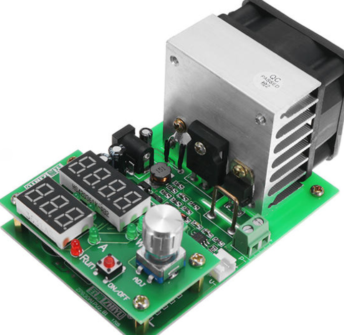
There is also the option of buying something cheap from the usual sources and hacking on some custom firmware to adapt it a little to your needs.


A Close Look At USB Power

It’s not a stretch to say that most devices these days have settled on USB as their power source of choice. While we imagine you’ll still be running into the occasional wall wart and barrel jack for the foreseeable future, at least we’re getting closer to a unified charging and power delivery technology. But are all USB chargers and cables created equal?

The answer, of course, is no. But the anecdotal information we all have about dud USB gear is just that, which is why [Igor Brkić] wanted to take a more scientific approach. Inspired by the lighting bolt icon the Raspberry Pi will flash on screen when the voltage drops too low, he set out to make a proper examination of various USB chargers and cables to see which ones aren’t carrying their weight.

In the first half of his investigation, [Igor] tests four fairly typical USB chargers with his TENMA 72-13200 electronic load. Two of them were name brand, and the other just cheap clones. He was surprised to find that all of the power supplies not only met their rated specifications, but in most cases, over-performed by a fair amount. For example the Lenovo branded charger that was rated for only 1 A was still putting out a solid 5 V at 1.7 A. Of course there’s no telling what would happen if you ran them that high for hours or days at a time, but it does speak to their short-term burst capability at least.

He then moved onto the USB cables, were things started to fall apart. The three generic cables saw significant voltage drops even at currents as low as 0.1 A, though the name brand cable with 20 AWG power wires did fare a bit better. But by .5 A they were all significantly below 5 V, and at 1 A, forget about it. Pulling anything more than that through these cables is a non-starter, and in general, you’ll need to put at least 5.2 V in if you want to actually run a USB device on the other side.

Admittedly this might not be groundbreaking research, but we appreciate [Igor] taking a scientific approach and tabulating all the information. If you’re still getting low voltage warnings on the Pi after swapping out your cheapo cables, then maybe the problem is actually elsewhere.

Custom Electronic Load Makes Use Of Gaming PC Tech

At first glance, you might think the piece of hardware pictured here is a modern gaming computer. It’s got water cooling, RGB LED lighting, and an ATX power supply, all of which happen to be mounted inside a flashy computer case complete with a clear window. In truth, it’s hard to see it as anything but a gaming PC.

In actuality, it’s an incredible custom electronic load that [EE for Everyone] has been developing over the last four months that’s been specifically designed to take advantage of all the cheap hardware out there intended for high-performance computers. After all, why scratch build a water cooling system or enclosure when there’s such a wide array of ready-made ones available online?

The “motherboard” with single load module installed.

Inside that fancy case is a large PCB taking the place of the original motherboard, to which four electronic load modules slot into. Each of these loads is designed to accept a standard Intel CPU cooler, be it the traditional heatsink and fan, or a water block for liquid cooling. With the current system installed [EE for Everyone] can push the individual modules up to 275 watts before the temperatures rise to unacceptable levels, though he’s hoping to push that a little higher with some future tweaks.

So what’s the end game here? Are we all expected to have a massive RGB-lit electronic load hidden under the bench? Not exactly. All of this has been part of an effort to design a highly accurate electronic load for the hobbyist which [EE for Everyone] refers to as the “Community Edition” of the project. Those smaller loads will be derived from the individual modules being used in this larger testing rig.

We’ve actually seen DIY liquid cooled electronic loads in the past, though this one certainly sets the bar quite a bit higher. For those with more meager requirements, you might consider flashing a cheap imported electronic load with an open source firmware to wring out some extra functionality.

Continue reading “Custom Electronic Load Makes Use Of Gaming PC Tech”

A DIY Electronic Load With A Twist

If you’re testing a power supply or battery pack, an electronic load is a nice tool to have. By watching the voltage as you crank up the resistance, you can verify the unit’s real-world capabilities quickly and easily. But [Xavier Bourlot] wanted a bit more information than is generally afforded by these devices, so he came up with his own scratch built load that can measure the voltage at multiple points in the circuit.

Now at first glance, it might not be obvious why you’d want such a capability. But [Xavier] is looking to do something very specific with this device: analyze the efficiency of DC-DC converters. The idea is that if the electronic load can measure the voltage on both sides of the converter, it can calculate what kind of losses are being incurred.

Could you do this with a multimeter and a traditional electronic load? Sure. But if it’s the kind of thing you’ll be doing a lot of, it’s not hard to see why this method would be preferable.

But even if you ignore the converter analysis capabilities, this looks to be a very useful device to have around the lab. [Xavier] says it can sink more than 5 amps, and handle an input voltage as high as 100 volts. Powered by an ATmega328P, the load is also fully programmable and even features an I2C expansion port that you can use to hang additional hardware or sensors on. The stock firmware is already quite capable, and the list of future enhancements has some very interesting entries such as the ability to log data over serial or to a SD card.

We’ve seen a number of programmable electronic load projects over the years, ranging from Arduino shields to VFD equipped units that would be the pride of any hacker’s bench.

Liquid Cooling Keeps This Electronic Load’s MOSFETs From Burning

Problem: your electronic load works fine, except for the occasional MOSFET bursting into flames. Solution: do what [tbladykas] did, and build a water-cooled electronic load.

One can quibble that perhaps there are other ways to go about preventing your MOSFETs from burning, including changes to the electrical design. But he decided to take a page from [Kerry Wong]’s design book and go big. [Kerry]’s electronic load was air-cooled and capable of sinking 100 amps; [tbladykas] only needed 60 or 70 amps or so. Since he had an all-in-one liquid CPU cooler on hand, it was only natural to use that for cooling.

The IXYS linear MOSFET dangles off the end of the controller PCB, where the TO-247 device is soldered directly to the copper cold plate of the AiO cooler. This might seem sketchy as the solder could melt if things got out of hand, but then again drilling and tapping the cold plate could lead to leakage of the thermal coupling fluid. It hasn’t had any rigorous testing yet – his guesstimate is 300 Watts dissipation at this point – but as his primary endpoint was to stop the MOSFET fires, the exact details aren’t that important.

We’ve seen a fair number of liquid-cooled Raspberry Pis and Arduinos before, but we can’t find an example of a liquid-cooled electronic load. Perhaps [tbladykas] is onto something with this design.

Spot This DIY Electronic Load’s Gracefully Hidden Hacks

Sometimes it’s necessary to make do with whatever parts one has on hand, but the results of squashing a square peg into a round hole are not always as elegant as [Juan Gg]’s programmable DC load with rotary encoder. [Juan] took a design for a programmable DC load and made it his own in quite a few different ways, including a slick 3D-printed enclosure and color faceplate.

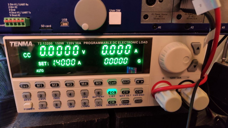
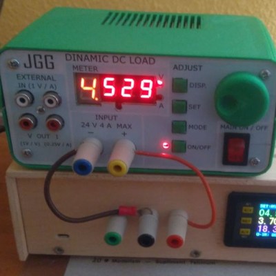
The first thing to catch one’s eye might be that leftmost seven-segment digit. There is a simple reason it doesn’t match its neighbors: [Juan] had to use what he had available, and that meant a mismatched digit. Fortunately, 3D printing one’s own enclosure meant it could be gracefully worked into the design, instead of getting a Dremel or utility knife involved. The next is a bit less obvious: the display lacked a decimal point in the second digit position, so an LED tucked in underneath does the job. Finally, the knob on the right could reasonably be thought to be a rotary encoder, but it’s actually connected to a small DC motor. By biasing the motor with a small DC voltage applied to one lead and reading the resulting voltage from the other, the knob’s speed and direction can be detected, doing a serviceable job as rotary encoder substitute.

The project’s GitHub repository contains the Arduino code for [Juan]’s project, which has its roots in a design EEVblog detailed for an electronic load. For those of you who prefer your DIY rotary encoders to send discrete clicks and pulses instead of an analog voltage, a 3D printed wheel and two microswitches will do the job.

ZPB30A1 Electronic Load Gets An Open Firmware

Importing cheap equipment and test gear is something of a mixed blessing. It allows you to outfit your lab without emptying your bank account, but on the other hand there’s usually a reason it’s cheap. Of course, the retail price of a piece of hardware shouldn’t be the metric by which we measure its quality, but there’s got to be a few corners cut someplace when they are selling this stuff for a fraction of what the name brands are charging.

A perfect example is the ZHIYU ZPB30A1 electronic load, available from various online importers for about $30 USD. While the price is right for an adjustable load that can handle up to 110 W, it’s got some pretty glaring shortcomings. In an effort to address at least some of those issues, [Luca Zimmermann] has been working on an open source replacement firmware for the load’s STM8S microcontroller.

[Luca] quickly discovered that the device’s STM8S005K6 chip is write protected, so unfortunately you can’t just flash a new firmware to it. If you want to unlock additional features, you need to perform a brain transplant. Luckily these chips are quite cheap, and you can probably add a couple of them to your cart when you order he ZPB30A1.

With the new GPLv3 licensed firmware installed, the device gains constant power and resistances modes (stock firmware can only do constant current), serial logging, and support for adjusting the value of the shunt resistor. There’s even a basic menu system to shuffle through the new modes. There’s still a couple features that haven’t been implemented, such as automatic shutdown, but it’s already a considerable upgrade from the stock software. Now we just need some details on the slick custom enclosure that [Luca] has put his upgraded ZPB30A1 into.

If this looks too easy, you can always go the DIY Arduino route for your load testing needs, or build a monster than can sink up to 1 kW.

[Thanks to Benik3 for the tip.]