The F Number On A Lens Means Something? Who Knew!

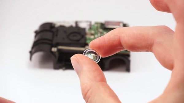
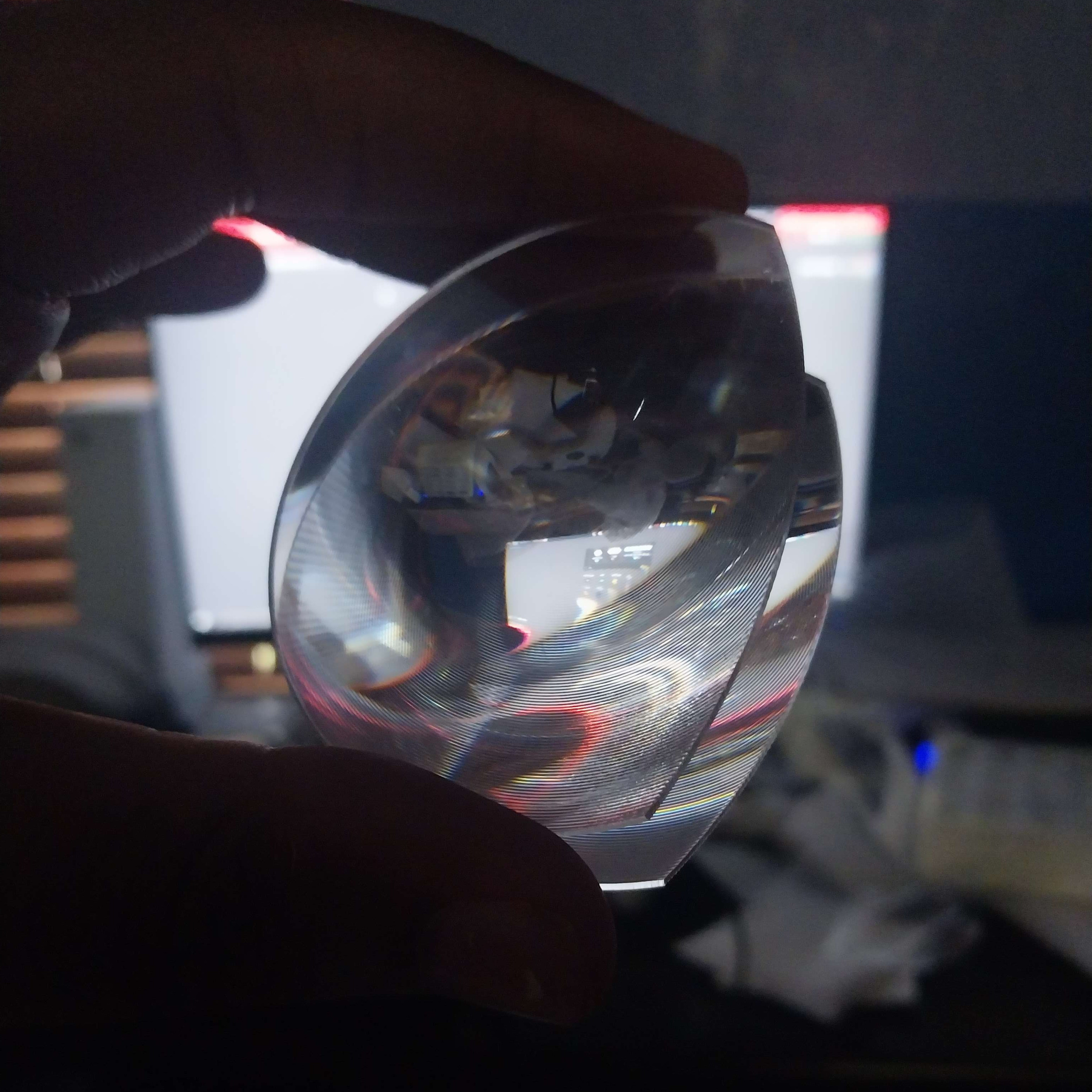
The Raspberry Pi has provided experimenters with many channels of enquiry, and for me perhaps the furthest into uncharted waters it has led me has come through its camera interface. At a superficial level I can plug in one of the ready-made modules with a built-in tiny lens, but as I experiment with the naked sensors of the HD module and a deconstructed Chinese miniature sensor it’s taken me further into camera design than I’d expected.

I’m using them with extra lenses to make full-frame captures of vintage film cameras, in the first instance 8 mm movie cameras but as I experiment more, even 35 mm still cameras. As I’m now channeling the light-gathering ability of a relatively huge area of 1970s glass into a tiny sensor designed for a miniature lens, I’m discovering that maybe too much light is not a good thing. At this point instead of winging it I found it was maybe a good idea to learn a bit about lenses, and that’s how I started to understand what those F-numbers mean.

More Than The Ring You Twiddle To Get The Exposure Right

lose-up of the end of a lens, showing the F-number range
The F-number range of a 1990s Sigma consumer-grade zoom lens.

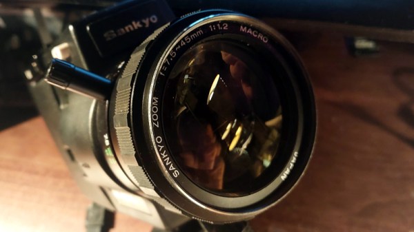
I’m not a photographer, instead I’m an engineer who likes tinkering with cameras and who takes photographs as part of her work but using the camera as a tool. Thus the f-stop ring has always been for me simply the thing you twiddle when you want to bring the exposure into range, and which has an effect on depth of field.

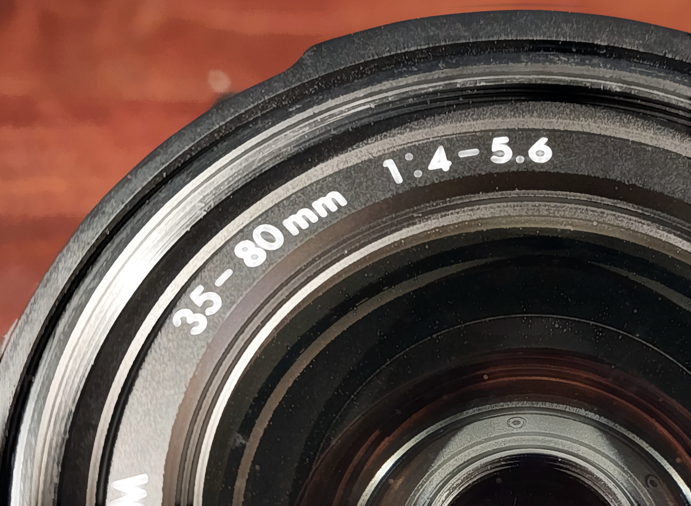
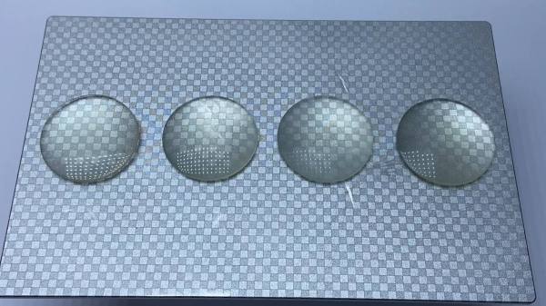
The numbers were always just numbers, until suddenly I had to understand them for my projects to work. So the first number I had to learn about was the F-number of the lens itself. It’s usually printed on the front next to the focal length and expressed as a ratio of the diameter of the light entrance to the lens focal length. Looking around my bench I see numbers ranging from 1:1 for a Canon 8mm camera to 1:2.8 for a 1950s Braun Paxette 35 mm camera, but it seems that around 1:1.2 is where most 8 mm cameras sit and 1:2 is around where I’m seeing 35 mm kit lenses. The F-stop ring controls an adjustable aperture, and the numbers correspond to that ratio. So that 1:2 kit lens is only 1:2 at the F2 setting, and becomes 1:16 at the F16 setting.

Fighting Too Much Light

A close-up of a 3d printed Super 8 cartridge in a camera, with a Raspberry Pi Zero 2 and a little M12 camera in it.
My Raspberry Pi camera is focused on the focal plane of a Minolta Super 8 movie camera.

My problem is that I’m trying to match a CMOS sensor with a very high sensitivity per unit area against lens systems designed for film, which at the relatively low ISO numbers of 8 mm movie film, has a much lower sensitivity per unit area. 8 mm film is a fantastic medium which provides an aesthetic like no other, but even its most diehard adherent wouldn’t disagree that light levels are of huge importance when using it.

I had some failed experiments with putting the CMOS sensor at the focal point of the camera, but in the end found a far more effective technique of using an M12 screw-in lens as a macro lens to focus on the original focal point from behind. This is great, but has the result that all of that extra light intended for an ISO 50 frame of 8 mm movie film instead lands on a Raspberry Pi sensor designed for a much smaller lens. I need to make it deliver equivalent light to that F number being much higher, but I want my digital cartridge to just drop into an unmodified camera, so I can’t mess about with camera apertures. The solution is to apply a neutral density filter, in effect an attenuator, to the front lens ring. Not ideal, but it’s the best I’ve got.

So this has been my journey into the numbers on the front of a camera lens, and also my journey into understanding how they help me in merging old and new cameras on the cheap. If you’re a seasoned photographer you’ll be wondering how it took me so long, but I hope some of you will have learned something new. If one day I can film a Hackaday report on a vintage Super 8 camera with a digital cartridge, it will all have been worthwhile.

A 3D Printed Grinder For Printed Lens Blanks

When one thinks of applications for 3D printing, optical components don’t seem to be a good fit. With the possible exception of Fresnel lenses, FDM printing doesn’t seem up to the job of getting the smooth surfaces and precision dimensions needed to focus light. Resin printing might be a little closer to the mark, but there’s still a long way to go between a printed blank and a finished lens.

That gap is what [Fraens] aims to fill with this homebrew lens grinding machine. It uses the same basic methods used to grind and polish lenses for centuries, only with printed components and lens blanks. The machine itself consists of a motorized chuck for holding the lens blank, plus an articulated arm to hold the polishing tool. The tool arm has an eccentric drive that wobbles the polishing tool back and forth across the blank while it rotates in the chuck. Lens grinding requires a lot of water and abrasive, so a large bowl is provided to catch the swarf and keep the work area clean.

Lens blanks are printed to approximately their finished dimensions using clear resin in an SLA printer. [Fraens] spent a lot of time optimizing the printing geometry to minimize the number of print layers required. He found that a 30° angle between the lens and the resin pool worked best, resulting in the clearest blanks. To polish the rough blanks, a lapping tool is made from polymer modeling clay; after baking it dry, the tool can hold a variety of pads and polishing compounds. From there it’s just a matter of running the blank through a range of abrasives to get the desired final surface.

Are the lenses fantastic? Well, they’re probably not going to make it into fine optical equipment, but they’re a lot better than you might expect. Of course, there’s plenty of room for improvement; better resins might result in clearer blanks, and perhaps degassing the uncured resin under vacuum might help with bubbles. Skipping the printed blanks and going with CNC-machined acrylic might be worth a try, too.

Continue reading “A 3D Printed Grinder For Printed Lens Blanks”

A wooden frame with 64 green LEDs running a Game of Life simulation

Wooden CNC Sculpture Displays Conway’s Game Of Life

Conway’s Game of Life has been the object of fascination for computer hobbyists for decades. Watching the generations tick by is mesmerizing to watch, but programming the data structure and implementing the rules is also a rewarding experience, especially if you’re just getting acquainted with a new computing platform. Just as rewarding can be creating a nice piece of hardware to run the game on, as [SandwichRising] has just done: check out his beautiful wooden Game of Life implementation.

A set of PCBs implementing an 8x8 LED displayThe main part of his Game is a piece of poplar wood that was CNC routed to produce an 8×8 display adorned with neat chain-like shapes. The display consists of standard 5 mm green LEDs, but they’re not the things you see poking out the front of the wooden frame. Instead, what you’re seeing are 64 lenses made out of epoxy. [SandwichRising] first covered the holes with tape, then poured green epoxy into each one and waited for it to harden. He then took off the tape and applied a drop of UV-cured epoxy on top to create a lens.

All the LEDs are mounted on PCB strips that are hooked up to a central bus going to the main ATmega328P  microcontroller sitting on a separate piece of PCB. Whenever the system is powered on, the game is set to a random state determined by noise, after which the simulation begins. On such a small field it’s pretty common for the game to end up in a stable state or a regular oscillation, which is why the ATmega keeps track of the last few dozen states to determine if this has happened, and if so, reset the game to a random state again.

The source code, as well as .STL files for the PCBs and the frame, are available in the project’s GitHub repository. If woodworking isn’t your thing, there’s plenty of other ways to make neat Game of Life displays, such as inside an alarm clock, with lots of LEDS under a coffee table, or even with a giant flip-dot display.

Making Your Own VR Headset? Consider This DIY Lens Design

Lenses are a necessary part of any head-mounted display, but unfortunately, they aren’t always easy to source. Taking them out of an existing headset is one option, but one may wish for a more customized approach, and that’s where [WalkerDev]’s homebrewed “pancake” lenses might come in handy.

Engineering is all about trade-offs, and that’s especially true in VR headset design. Pancake lenses are compact units that rely on polarization to bounce light around internally, resulting in a very compact assembly at the cost of relatively poor light efficiency. That compactness is what [WalkerDev] found attractive, and in the process discovered that stacking two different Fresnel lenses and putting them in a 3D printed housing yielded a very compact pancake-like unit that gave encouraging results.

This project is still in development, and while the original lens assembly is detailed in this build log, there are some potential improvements to be made, so stay tuned if you’re interested in using this design. A DIY headset doesn’t mean you also must DIY the lenses entirely from scratch, and this option seems economical enough to warrant following up.

Want to experiment with mixing and matching optics on your own? Not only has [WalkerDev]’s project shown that off-the-shelf Fresnel lenses can be put to use, it’s in a way good news that phone-based VR is dead. Google shipped over 10 million cardboard headsets and Gear VR sold over 5 million units, which means there are a whole lot of lenses in empty headsets laying around, waiting to be harvested and repurposed.

A Wigglegram Lens With Variable Aperture

Wigglegrams are those weird animated pictures you’ve seen that seem to generate a 3D-like effect. [scealux] had built lenses to take such pictures before, but wanted to take things to the next level. Enter the Wigglegram Lens, version 2.

In building a new lens for the Open Sauce ’23 event, [scealux] wanted to get variable aperture working, while also improving focus speed. The lens was also intended for use with a Sony A7R3. Unlike his previous effort, this lens would only work on the full-frame Sony FE mount cameras.

The lens uses a bevy of 3D printed parts, along with plastic lenses salvaged from old disposable cameras. When assembled, it takes three photos simultaneously on one single frame. They can then be reassembled into a Wigglegram by post-processing on a computer. The results are grainy and rough, but yet somehow compelling.

If you want to see [scealux]’s original build for Sony E-mount cameras, we covered it here. Video after the break.

Continue reading “A Wigglegram Lens With Variable Aperture”

Probably The Cheapest Lens You Will Ever Use

Photographic enthusiasts will invariably amass an extensive collection of lenses, and in their communities there are near-mythical and sought-after lenses that change hands for incredible prices. It’s probably the oldest photographic adage though, that the best camera in the world is the one in your hand when the scene presents itself, and probably one of the simplest cameras in the world remains the disposable film camera. Their tiny plastic lenses are not in the same league as the pricey ones, but can they be used by a more serious photographer? [Volzo] set out to find out.

Disposable cameras aren’t the most environmentally friendly items, and he rightly points out that a cheap compact camera can deliver the same in a more sustainable package. There’s also the point to make that the flash capacitor if it has one can deliver a nasty shock, but once past that it’s easy to remove the lens itself.

A single element lens brings with it some significant distortion, and it’s a surprise to find that the focal plane of a disposable camera is curved to take account of that. His first 3D printed mount and adapter for a Sony mirrorless compact camera uses a small aperture to reduce the distortion effects from the edge of the lens but he’s not out of tricks yet. Using a pair of the lenses back-to-back he halves the focal length but further corrects the distortion and delivers a consequent wider angle. Take a look, in the video below.

The result is a usable lens for the toy-camera look on your digital camera, and since the files can all be found at the link above it’s something you can try too. If a disposable camera comes our way, we certainly will.

This isn’t the first disposable camera lens project we’ve brought you.

Continue reading “Probably The Cheapest Lens You Will Ever Use”

Make Yourself A Megamind With A Hypercentric Camera

Sometimes, all it takes to learn something new is a fresh perspective on things. But what’s to be learned from reversing your perspective completely with a hypercentric lens? For one thing, that you can make humans look really, really weird.

To be fair, there’s a lot to the optical story here, which [volzo] goes over in ample detail. The short version of it is that with the right arrangement of optical elements, it’s possible to manipulate the perspective of a photograph for artistic effect, up to the point of reversing the usual diminishment of the apparent size of objects in the scene that are farther away from the camera. Most lenses do their best to keep the perspective of the scene out of this uncanny valley, although the telecentric lenses used in some machine vision systems manipulate the perspective to make identical objects within the scene appear to be the same size regardless of their distance from the camera. A hypercentric lens, on the other hand, turns perspective on its head, making near objects appear smaller than far objects, and comically distorts things like the human face.

[volzo]’s hypercentric camera uses a 700-mm focal length Fresnel lens mounted on a motorized gantry, which precisely positions a camera relative to the lens to get the right effect. A Raspberry Pi controls the gantry, but it’s not strictly needed for the hypercentric effect to work. Lighting is important, though, with a ring of LEDs around the main lens providing even illumination of the scene. The whole setup as well as the weirdly distorted portraits that result are shown in the video below.

If these bizarrely distorted faces look familiar, you might be recalling [Curious Marc]’s head-enlarging wearable.

Continue reading “Make Yourself A Megamind With A Hypercentric Camera”