Solder Two Boards At Once With This Dual Reflow Plate

Homebrew reflow projects generally follow a pretty simple formula: find a thrift shop toaster oven or hot plate, add a microcontroller and a means to turn the heating element on and off, and close the loop with a thermistor. Add a little code and you’re melting solder paste. Sometimes, though, a ground-up design works better, like this scalable reflow plate with all the bells and whistles.

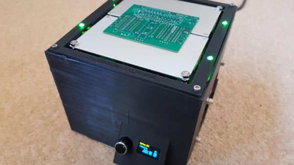
Now, we don’t mean to hate on the many great reflow projects we’ve seen, of course. But [Michael Benn]’s build is pretty slick. The business end uses 400-watt positive temperature coefficient (PTC) heating elements from Amazon controlled by solid-state relays, although we have to note that we couldn’t find the equivalent parts on the Amazon US site, so that might be a problem. [Michael] also included mechanical temperature cutoffs for each plate, an essential safety feature in case of thermal runaway. The plates are mounted at the top of a 3D-printed case, which also has an angled enclosure for a two-color OLED display and a rotary encoder.

The software runs on an ESP32 and supports multiple temperature profiles for different solder pastes. The software also supports different profiles on the two plates, and even allows for physical expansion to a maximum of four heating plates, or even just a single plate if that’s what you need. The video below shows it going through its paces along with the final results. There’s also a video showing the internals if that’s more your style

We appreciate the fit and finish here, as well as the attention to safety. Can’t find those heating elements for your build? You might have to lose your appetite for waffles.

Continue reading “Solder Two Boards At Once With This Dual Reflow Plate”

An LM386 Oscillator Thanks To Tungsten Under Glass

Once ubiquitous, the incandescent light bulb has become something of a lucerna non grata lately. Banned from home lighting, long gone from flashlights, and laughed out of existence by automotive engineers, you have to go a long way these days to find something that still uses a tungsten filament.

Strangely enough, this lamp-stabilized LM386 Wien bridge oscillator is one place where an incandescent bulb makes an appearance. The Wien bridge itself goes back to the 1890s when it was developed for impedance measurements, and its use in the feedback circuits of vacuum tube oscillators dates back to the 1930s. The incandescent bulb is used in the negative feedback path as an automatic gain control; the tungsten filament’s initial low resistance makes for high gain to kick off oscillation, after which it heats up and lowers the resistance to stabilize the oscillation.

For [Grug Huler], this was one of those “just for funsies” projects stemming from a data sheet example circuit showing a bulb-stabilized LM386 audio oscillator. He actually found it difficult to source the specified lamp — there’s that anti-tungsten bias again — but still managed to cobble together a working audio oscillator. The first pass actually came in pretty close to spec — 1.18 kHz compared to the predicted 1.07 kHz — and the scope showed a very nice-looking sine wave. We were honestly a bit surprised that the FFT analysis showed as many harmonics as it did, but all things considered, the oscillator performed pretty well, especially after a little more tweaking. And no, the light bulb never actually lights up.

Thanks to [Grug] for going down this particular rabbit hole and sharing what he learned. We love builds like this that unearth seemingly obsolete circuits and bring them back to life with modern components. OK, calling the LM386 a modern component might be stretching things a bit, but it is [Elliot]’s favorite chip for a reason.

Continue reading “An LM386 Oscillator Thanks To Tungsten Under Glass”

Test Unknown Fuses Without Destroying Them

There’s a problem with fuses. On the face of it, testing would seem to be a one-shot deal — exceed the rated current and see if it blows. But once you know the answer, the device is useless. If only there were a way to test fuses without damaging them.

As it turns out there is, and [Kerry Wong] weaves quite a tale about his attempts to non-destructively test fuses. The fuses in question are nothing fancy — just the standard glass tube type, from a cheap assortment kit off Amazon. Therein lies the problem: can such cheap devices be trusted? Finding out requires diving much deeper into the technology of fuses than many people will have done, including understanding how the thermal and electrical characteristics of the fuse element behave.

[Kerry]’s test setup is simple, consisting of a constant current power supply and a voltmeter across the fuse to measure the voltage drop caused by the resistance of the fuse element. As he ramps up the current, the voltage drop increases linearly due to the increase in resistance of the alloy with increasing temperature. That only lasts up to a point, where the fuse resistance starts increasing exponentially. Pushing much past the point where the resistance has doubled would blow the fuse, so that’s the endpoint of his tests. Perhaps unsurprisingly, his no-name fuses all went significantly beyond their rated current, proving that you get what you pay for. See the video below for the tests and an analysis of the results.

It’s handy to know there’s a way to check fuses without popping them, and we’ll file this one away for future reference. Don’t forget that you should always check the fuse when troubleshooting, because you never know what the last person did to it.

Continue reading “Test Unknown Fuses Without Destroying Them”

Teardown Of A Cheap Glue Gun

A hot glue gun is one of those standard tools of the hardware hacker’s bench, called upon to provide adhesion between an astonishing range of materials, and to provide a handy filler and strain relief in the form of blobs of polymer glue. We’ve all got one, but how many of us have taken a look inside it?

[Andrew Lorimer] bought a super-cheap eBay glue gun, and subjected it to a teardown. As you might expect, he found it to be a pretty simple device with only a trigger mechanism and a dumb heating element, but his write-up is of passing interest because he’s characterised its heating element. It has a positive temperature coefficient, which means that its resistance increases from around 2.5 kΩ at room temperature to about 7 kΩ at its 150 ºC operating temperature. This limits the current, and provides a very simple thermostat action.

The build quality is surprisingly good for such a cheap appliance, and he notes a surfeit of screws holding its shell together. But the quality of the insulation and strain relief leaves a lot to be desired, and he wonders whether it truly qualifies for its double-insulated logo. The LED pilot light is simply fed from the 240 V mains supply through a 250 kΩ resistor which he replaces with a 12 kΩ component for a brighter result.

We cover plenty of teardowns here at Hackaday. Often they are of extremely expensive and complex devices, but sometimes they are of much simpler subjects.

PTC Heaters For Reflow Soldering

Reflow soldering – setting components on a PCB in blobs of solder paste and heating the whole assembly at once to melt all joints simultaneously – has been the subject of many ingenious hacks. Once it was the sole preserve of industrial users with specialist microprocessor-controlled ovens, now there are a myriad Arduino-controlled toaster ovens, hot air blowers, and hotplates that allow hackers and makers to get in on the reflow act too.

This morning a fresh idea in the reflow soldering arena has come our way. It’s not the most earth-shattering, but it does have some advantages so is worth a second look. [Analog Two] has successfully used a PTC heating element as a reflow soldering hotplate.

PTC heating elements are thermistors with a positive temperature coefficient. As their temperature rises, so does their electrical resistance. By careful selection of materials they can be manufactured with a sharp increase in resistance at a particular temperature. Thus when an electrical current is passed through them they heat up until they reach that temperature, then the current decreases as the resistance goes up, and they do not heat beyond that point. Thus as heaters they are intrinsically self-regulating. From our point of view they have another advantage, they are also cheap. Fitted as they are to thousands of domestic heating products they are readily available, indeed [Analog Two] found his on Amazon.

The heater chosen was a 200W 110V model with a temperature of 230 Celcius to match the solder he was using. They are also available for other mains voltages, and even at 12 and 24V for automotive applications. He reports that the time to reflow was about 90 seconds.

We’ve mentioned the advantages of this heater as its price and regulated temperature. Looking at the pictures though a disadvantage is its size. This is a reflow plate for small boards. There are larger PTC heater elements available though, it would be interesting to hear people’s experiences reflowing with them.

Hotplates for reflow soldering have featured before a few times here at Hackaday. We recently had this tiny plate, but we’ve also had a PID-controlled plate, and an Arduino-controlled domestic hotplate. We’re sure this is an avenue with further to go.

Wax Motors Add Motion To Your Projects

[electronicsNmore] has uploaded a great teardown and tutorial video (YouTube link) about wax motors. Electric wax motors aren’t common in hobby electronics, but they are common in the appliance industry, which means the motors can be often be obtained cheaply or for free from discarded appliances. Non-electric wax motors have been used as automotive coolant thermostats for years.  Who knows, this may be just what the doctor ordered for your next project.

As [electronicsNmore] explains, wax motors are rather simple devices. A small block of wax is sealed in a metal container with a movable piston. When heated, the wax expands and pushes the piston out. Once the wax cools, a spring helps to pull the piston back in.

The real trick is creating a motor which will heat up without cooking itself. This is done with a Positive Temperature Coefficient (PTC) thermistor. As the name implies, a PTC thermistor’s resistance increases as it heats up. This is the exact opposite of the Negative Temperature Coefficient (NTC) thermistors we often use as temperature sensors. PTC’s are often found in places like power supplies to limit in rush current, or small heating systems, as we have in our wax motor.

As the PTC heats up, its resistance increases until it stops heating. At the same time, the wax is being warmed, which drives out the piston. As you might expect, wax motors aren’t exactly efficient devices. The motor in  [electronicsNmore’s] video runs on 120 volts AC. They do have some advantages over solenoid, though. Wax motors provide smooth, slow operation. Since they are resistive devices, they also don’t require flyback diodes, or create the RF noise that a solenoid would.

Continue reading “Wax Motors Add Motion To Your Projects”