A graphic showing the suggested footprint dimensions for 0402 parts

Want Better 0402 Reflow? Consider These Footprints!

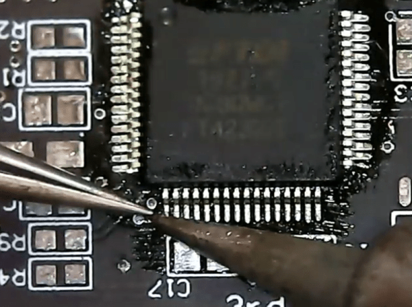
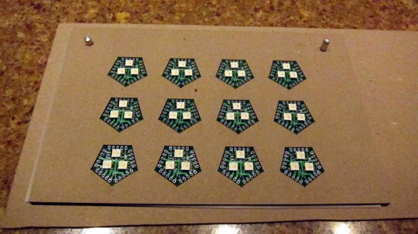
Assembling with a stencil is just that much more convenient – it’s a huge timesaver, and your components no longer need to be individually touched with a soldering iron for as many times as they have pads. Plus, it usually goes silky smooth, the process is a joy to witness, and the PCB looks fantastic afterwards! However, sometimes components won’t magically snap into place, and each mis-aligned resistor on a freshly assembled board means extra time spent reflowing the component manually, as well as potential for silent failures later on. In an effort to get the overall failure rate down, you will find yourself tweaking seemingly insignificant parameters, and [Worthington Assembly] proposes that you reconsider your 0402 and 0201 footprints.

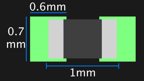
Over the years, they noticed a difference in failure rates between resistor&capacitor footprints on various boards coming in for assembly – the size and positioning of the footprint pads turned out to be quite significant in reducing failure rate, even on a tenth of millimeter scale. Eagle CAD default footprints in particular were a problem, while a particular kind of footprint never gave them grief – and that’s the one they recommend we use. Seeing the blog post become popular, they decided to share their observations on 0201 as well, and a footprint recommendation too. Are your 0402 resistors giving you grief? Perhaps, checking the footprints you’re using is a good first step.

The 0402 and 0201 components are in a weird spot, where soldering iron assembly is no longer really viable, but the stencil+reflow approach might not be unilaterally successful when you start off – fortunately, that’s where writeups like these come in. Interested in learning stenciling? Get some solder paste, and read up on all the different ways you can put it onto your boards.

PCB Hotplate Has Integrated Heating Element Traces

Normally when we talk about PCBs and hotplates, we’re talking about reflowing solder. In this build from [Arnov Sharma], though, the PCB itself is the hotplate!

The idea was to create a compact hotplate for easily reflowing small PCBs. To achieve that, [Arnov] designed a board with a thick coil trace that acts as a heating element. The full coil trace has a resistance of 1.9 ohms, and passing electricity through it generates plenty of heat. Running off a 12 volt supply, the mini hotplate is capable of reaching a maximum temperature of 214°C. Higher voltages can push that figure higher.

The board is intended to self-regulate, with an ATtiny13 onboard and a thermistor to measure temperature. However, in the initial design, this feature didn’t quite work properly. Version 2 is intended to include a better temperature sensor and a OLED screen for displaying the current temperature to the user.

We’ve seen other tiny hotplate builds before, too. They’re great for smaller projects and for hacking on the go! Video after the break.

Continue reading “PCB Hotplate Has Integrated Heating Element Traces”

CO2 laser cutting ceramic sheet under water film

Water Is The Secret Ingredient When Laser Cutting Ceramics To Make Circuits

[Ben Krasnow] over at Applied Science was experimenting with cutting inexpensive ceramic sheets with his cheap CO2 laser cutter when he found that (just as expected) the thermal shock of the CO2 beam would cause cracking and breaking of the workpiece. After much experimentation, he stumbled upon a simple solution: submersion under a thin layer of water was sufficient to remove excess heat, keeping thermal shock at bay, and eventually cutting the material. Some prior art was uncovered, which we believe is this PHD thesis (PDF) from Manchester University in the UK. This is a great read for anyone wanting to dig into this technique a little deeper.

The CO2 laser cutter is a very versatile tool, capable of cutting and etching a wide range of materials, many of natural origin, such as cardboard, leather and wood, as well as certain plastics and other synthetic materials. But, there are also materials that are generally a no-go, such as metals, ceramics and anything that does not absorb the laser wavelength adequately or is too reflective, so having another string in one’s bow is a good thing. After all, not everyone has access to a fibre laser.

After dispensing with the problem of how to cut ceramic, it got even more interesting. He proceeded to deposit conductive traces sufficiently robust to solder to. A mask was made from vinyl sheet and a squeegee used to deposit a thick layer of silver and glass particles 1 um or less in size. This was then sintered in a small kiln, which was controlled with a Raspberry Pi running PicoReFlow, and after a little bit of scrubbing, the surface resistance was a very usable 2 mΩ/square. Holes cut with the laser, together with some silver material being pushed through with the squeegee formed through holes with no additional effort. That’s pretty neat!

Some solder paste and parts were added to the demo board, and with an added flare for no real reason other than he could, reflowed by simply applying power direct to the board. A heater trace had been applied to the bottom surface, rendering the board capable of self-reflowing. Now that is cool!

Continue reading “Water Is The Secret Ingredient When Laser Cutting Ceramics To Make Circuits”

PCB Reflow With A PCB

We wonder if [Carl Bugeja] was looking at a 3D printer’s heated bed when he got the idea to create a PCB reflow heater using a PCB. He tried a quick test to heat up a standard PCB and made it self-reflow. That worked, though it obviously wouldn’t be practical for all boards. But it proved he could make it work.

To improve the heating performance, he laid out a metal core PCB, along with some custom control electronics. The board’s resistance didn’t quite perform to calculations, but luckily, it was too high so a shunt wire was able to reduce the overall resistance. One important thing to consider is that the heater board needs to use higher temperature solder so it doesn’t desolder its own components

We were glad to see [Carl] use a metal core board as standard PCB material can get cranky at high temperatures over 130C. Even so, it would be good to check the boards you plan to use this way to make sure they are rated for the kind of temperatures required.

We’ve seen lots of reflow heat sources. Halogen lights come to mind. Or, raid the toy closet and find an Easy Bake oven.

Continue reading “PCB Reflow With A PCB”

Can You Use An Easy-Bake Oven For Reflow Soldering?

The answer is yes, yes you can. As long as you have one made after about 2011, at least. In the video after the break, [Blitz City DIY] takes us briefly through the history of the venerable Easy-Bake Oven and into the future by reflow soldering a handful of small blinky boards with it.

You’re right, these things once used special light bulbs to cook pint-sized foods, but now they are legit ovens with heating elements that reach 350°F and a little above. The only trouble is that there’s no temperature controller, so you have to use low-temperature solder paste and an oven thermometer to know when to pull the little tray out. Other than that, it looked like smooth sailing.

If you’re only doing a board every once in a while, $40 for a reflow oven isn’t too shabby. And yeah, as with all ovens, once you’ve reflowed a board in it, don’t use it for food.

If you’d rather build an oven, high-powered light bulbs will still do the trick.

Continue reading “Can You Use An Easy-Bake Oven For Reflow Soldering?”

Robotics Club Teaches Soldering

Oregon State University must be a pretty good place to go to school if you want to hack on robots. Their robotics club, which looks active and impressive, has a multi-part video series on how to solder surface mount components that is worth watching. [Anthony] is the team lead for their Mars Rover team and he does the job with some pretty standard-looking tools.

The soldering station in use is a sub-$100 Aoyue with both a regular iron and hot air. There’s also a cheap USB microscope that looks like it has a screen, but is covered in blue tape to hold it to an optical microscope. So no exotic tools that you’d need a university affiliation to match.

Continue reading “Robotics Club Teaches Soldering”

Multi-Board Solder Stencils Explained

There was a time when reflow soldering was an impossibly exotic process at our level, something that only the most superhuman of hackers could even dream of attempting. But a demystification of the process plus the ready availability of affordable PCB and stencil manufacture has rendered into the range of almost all constructors, and it is likely that many of you reading this will have done it yourself.

Screen-printing solder paste onto a single board presents a mild alignment challenge, but how about doing it with many boards at once? [Eric Gunnerson] had this problem with a small-volume board he’s selling, and not being in the happy position of having his PCBs supplied on a panel, had to create his own multi-board alignment jig and stencil. His write-up provides a comprehensive and fascinating introduction to the process whether you are an occasional dabbler or embarking on a production run as he is.

The problem facing any would-be stenciler is that the board has to be held in place reliably in the same alignment as the stencil. With a single board, it’s easy enough to do the usual thing of taping scraps of PCB board to constrain its edges and hold it in place as a rudimentary jig, then lower the stencil onto it. Perhaps you’ve used one of those commercial stencil jigs, in which a set of magnets hold the stencil in place, or maybe you use pins to line everything up.

[Eric] takes us through the process of creating a laser-cut alignment jig for twelve boards, and cutting a matching twelve-board stencil. This includes all the software side using Inkscape, the selection of materials to match PCB thickness, and some of the issues with cutting Mylar sheet for the stencil without shrinkage at the corners. He’s using pins for alignment, and he even finds a handy supply of those in the form of shelf support pins.

We’ve visited the world of reflowing many times before. If you’d like a primer, here’s our Tools of the Trade piece on it, and if you aren’t daunted by larger projects, here’s an account of a prototype run of a significantly complex board.