The prolific [Peter Waldraff] is at back it with another gorgeous micro train layout. This time, there are no plugs and no batteries. And although it’s crank-powered, it can run on its own with the flip of a switch. How? With a supercapacitor, of course.
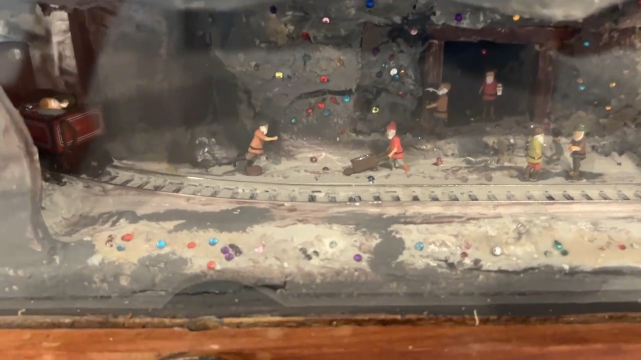 The crank handle is connected a 50 RPM motor that acts as a generator, producing the voltage necessary to both power the train and charge up the supercapacitor. As you’ll see in the video below, [Peter] only has to move the train back and forth about two or three times before he’s able to flip the switch and watch it run between the gem mine and the cliff by itself.
The supercapacitor also lights up the gem mine to show off the toiling dwarfs, and there’s a couple of reed switches at either end of the track and a relay that handles the auto-reverse capability. Be sure to stick around to the second half of the video where [Peter] shows how he built this entire thing — the box, the layout, and the circuit.
Want to see more of [Peter]’s trains and other work? Here you go.
Continue reading “Crank-Powered Train Uses No Batteries Or Plugs”