A 555-Shaped Discrete Component 555

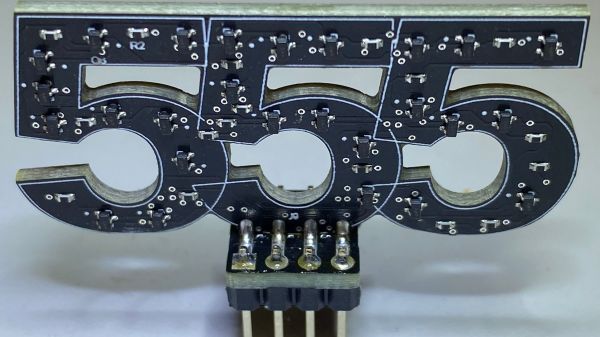
While the “should have used a 555” meme is strong around these parts, we absolutely agree with [Kelvin Brammer]’s decision to make this 555-shaped plug-in replacement for the 555 timer chip using discrete parts, rather than just a boring old chip.

As [Kelvin] relates, this project started a while back as an attempt to both learn EDA and teach students about the inner workings of the venerable timer chip. The result was a 555-equivalent circuit on a through-hole PCB, with the components nicely laid out into the IC’s functional blocks. As a bonus, the PCB was attached to an 8-pin header which could be plugged right in as a direct replacement for the chip.

Fast forward a few years, and [Kelvin] needed to learn yet another EDA package; what better way than to repeat the 555 project? It was also a good time to step into SMD design, as well as add a little zazzle. While the updated circuit isn’t as illustrative of the internal arrangement of the 555, the visual celebration of the “triple nickel” is more than worth it. And, just like the earlier version, this one has a header so you can just plug and chug — with style.

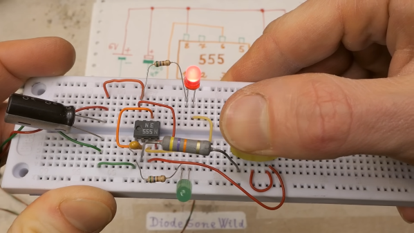
Want to know how the 555 came to be? We’ve covered that. You can also look at some basic 555 circuits to put your 555-shaped 555 to work. We’ve even seen a vacuum tube 555 if that’s more your thing.

Back To Basics With A 555 Deep Dive

Many of us could sit down at the bench and whip up a 555 circuit from memory. It’s really not that hard, which is a bit strange considering how flexible the ubiquitous chip is, and how many ways it can be wired up. But when was the last time you sat down and really thought about what goes on inside that little fleck of silicon?

If it’s been a while, then [DiodeGoneWild]’s back-to-basics exploration of the 555 is worth a look. At first glance, this is just a quick blinkenlights build, which is completely the point of the exercise. By focusing on the simplest 555 circuits, [Diode] can show just what each pin on the chip does, using an outsized schematic that reflects exactly what’s going on with the breadboarded circuit. Most of the demos use the timer chip in free-running mode, but circuits using bistable and monostable modes sneak in at the end too.

Yes, this is basic stuff, but there’s a lot of value in looking at things like this with a fresh set of eyes. We’re impressed by [DiodeGoneWild]’s presentation; while most 555 tutorials focus on component selection and which pins to connect to what, this one takes the time to tell you why each component makes sense, and how the values affect the final result.

Curious about how the 555 came about? We’ve got the inside scoop on that.

Continue reading “Back To Basics With A 555 Deep Dive”

Two-Channel Guitar Stomp Box Makes Momentary Switches Latching

When we first saw [Maarten Tromp]’s article about a “momentary latching switch” for guitar effects pedals, we have to admit to being a bit confused. When it comes to push-button switches, “momentary” and “latching” seem to be at odds with each other, with different mechanisms inside the switch to turn one into the other. What gives?

As it turns out, [Maarten]’s build makes perfect sense when you consider the demands of a musical performance. Guitar effects pedals, or “stomp boxes,” are often added to the output of electric guitars and other instruments to change the signals in some musically interesting way. The trouble is, sometimes you only need an effect for a few bars, and the push-on, push-off switches on many effects pedals make that awkward.

[Maarten]’s idea was to build a stomp box with momentary switches that act as inputs to an ATtiny2313 microcontroller rather than directly controlling the effect. That way, a bit of code can determine how long the switch is tapped, and activate a relay to do the actual switching accordingly. A short tap of the button tells the microcontroller to latch the relay closed until another tap comes along; a long press means that the relay is held open only as long as the button is held down.

Yes, he could have used a 555, a fact which [Maarten] readily acknowledges, but with some loss of flexibility; he currently has the threshold set at 250 milliseconds, which works for his performance style. Changing it would be a snap in code, as would toggling the latching logic. A microcontroller also makes expansion from the two-channel setup shown here easier.

Looking for more effects pedal action? We’ve got a bunch — a tube-amp tremolo, an Arduino Mega multipedal, a digital delay line. Take your pick!

Hackaday Links Column Banner

Hackaday Links: August 20, 2023

In some ways, we’ve become a little jaded when it comes to news from Mars, which almost always has to do with the Ingenuity helicopter completing yet another successful flight. And so it was with the report of flight number 54 — almost. It turns out that the previous flight, which was conducted on July 22, suffered a glitch that cut the flight short by forcing an immediate landing. We had either completely missed that in the news, or NASA wasn’t forthcoming with the news, perhaps until they knew more. But the details of the error are interesting and appear related to a glitch that happened 46 flights before, way back in May of 2021, that involves dropped frames from the video coming from the helicopter’s down-facing navigational camera. When this first cropped up back on flight six, it was only a couple of missed frames that nearly crashed the craft, thanks to confusion between the video stream and the inertial data. Flight engineers updated the aircraft’s software to allow for a little more flexibility with dropped frames, which worked perfectly up until the aborted flight 53.

Continue reading “Hackaday Links: August 20, 2023”

Should’ve Used A 555 — Or 276 Of Them

When asked to whip up a simple egg timer, most of us could probably come up with a quick design based on the ubiquitous 555 timer. Add a couple of passives around the little eight-pin DIP, put an LED on it to show when time runs out, and maybe even add a pot for variable timing intervals if we’re feeling fancy. Heck, many of us could do it from memory.

So why exactly did [Jesse Farrell] manage to do essentially the same thing using a whopping 276 555s? Easy — because why not? Originally started as an entry in the latest iteration of our 555 Contest, [Jesse]’s goal was simple — build a functional timer with a digital display using nothing but 555s and the necessary passives. He ended up needing a few transistors and diodes to pull it off, but that’s a minor concession when you consider how many chips he replaced with 555s, including counters, decoders, multiplexers, and display drivers. All these chips were built up from basic logic gates, a latch, and a flip-flop, all made from one or more 555s, or variants like the 556 or 558.

As one can imagine, 276 chips take a lot of real estate, and it took eleven PCBs to complete the timer. A main board acts as the timer’s control panel as well as serving as a motherboard for ten other cards, each devoted to a different block of functions. It’s all neat and tidy, and very well-executed, which is in keeping with the excellent documentation [Jesse] produced. The whole thing is wonderfully, needlessly complex, and we couldn’t be more tickled to feature it.

Continue reading “Should’ve Used A 555 — Or 276 Of Them”