Printed Jig Is A Welding Rig

[NixieGuy] was scheming to build robots with cable-driven joints when the pandemic hit. Now that component sourcing is scarce, he’s had to get creative when it comes to continuous cables. These cables need to be as seamless as possible to avoid getting caught on the pulleys, so [Nixie] came up with a way to weld together something he already has on hand — lengths of .45mm steel cable.

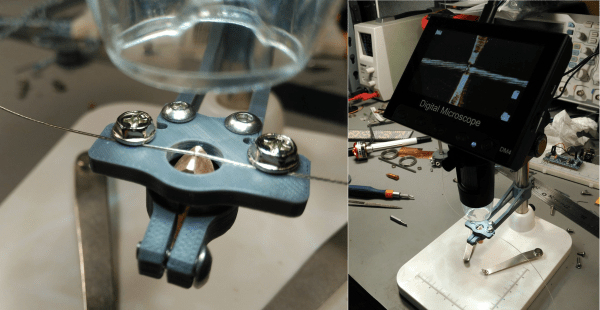
The 3D printed jig is designed to be used under a digital microscope, and even clamps to the pillar with screws. Another set of screws holds the two wires in place while they are butt welded between two pieces of copper.

[Nixie] adds a spot of solder paste for good measure, and then joins the wires by attaching his bench power supply set to 20V @ 3.5A to the copper electrodes. We love that [Nixie] took the time to streamline the jig design, because it looks great.

This just goes to show you that great things can happen with limited resources and a little bit of imagination. [Nixie] not only solved his own supply chain problem, he perfected a skill at the same time. If you don’t have a bench supply, you might be able to get away with a battery-powered spot welder, depending on your application.

Can Solder Paste Stencils Be 3D Printed? They Can!

3D printed solder paste stencil, closeup.

[Jan Mrázek]’s  success with 3D printing a solder paste stencil is awfully interesting, though he makes it clear that it is only a proof of concept. There are a lot of parts to this hack, so let’s step through them one at a time.

First of all, it turns out that converting a PCB solder paste layer into a 3D model is a bit of a challenge. A tool [Jan] found online didn’t work out, so he turned to OpenSCAD and wrote a script (available on GitHub) which takes two DXF files as input: one for the board outline, and one for the hole pattern. If you’re using KiCad, he has a Python script (also on GitHub) which will export the necessary data.

The result is a 3D model that is like a solder paste mask combined with a raised border to match the board outline, so that the whole thing self-aligns by fitting on top of the PCB. A handy feature, for sure. [Jan] says the model pictured here printed in less than 10 minutes. Workflow-wise, that certainly compares favorably to waiting for a stencil to arrive in the mail. But how do the actual solder-pasting results compare?

3D printed solder stencil on PCB, after applying solder paste.

[Jan] says that the printed stencil had a few defects but it otherwise worked fine for 0.5 mm pitch ICs and 0402 resistors, and the fact that the 3D printed stencil self-registered onto the board was a welcome feature. That being said, it took a lot of work to get such results. [Jan]’s SLA printer is an Elegoo Mars, and he wasn’t able to have it create holes for 0.2 mm x 0.5 mm pads without first modifying his printer for better X/Y accuracy.

In the end, he admits that while a functional DIY solder stencil can be 3D printed in about 10 minutes, it’s not as though professionally-made stencils that give better results are particularly expensive or hard to get. Still, it’s a neat trick that could come in handy. Also, a quick reminder that we stepped through how to make a part in OpenSCAD in the past, which should help folks new to OpenSCAD make sense of [Jan]’s script.

DIY Dispenser Places Solder Paste Without The Mess

When doing surface-mount assembly you can certainly use a soldering iron in the traditional way, but it’s far more convenient to cover the pads with solder paste, place the components, and bake the board in a reflow oven. If you’re lucky enough to have a precut stencil this can be done in one go, otherwise a tiny blob of paste must be laboriously placed on each pad by hand. [Kevarek] has made this a bit easier by designing a low-cost handheld solder paste dispenser.

The unit takes the form of a handheld 3D printed wand containing a geared motor and a threaded shaft, that engages with a syringe full of paste clamped onto its end. There’s a control box powered by an STM32 microcontroller that not only allows adjustment of flow rate, but provides advanced features such as performing a slight retraction at the end of dispensing to avoid excess paste. There’s a push-button on the wand for control, as well as a set on the control box to adjust its parameters.

If you’ve ever handled solder paste, you’ll know it can be a uniquely annoying and finicky substance. Either it’s too stiff and clumps together, or too runny and spreads out. No doubt some readers are lucky enough to always have fresh paste of the highest quality to hand, but too often a hackerspace will have a tub of grey goop with uncertain provenance. We like this tool, and while it won’t make up for poor quality or badly stored paste, at least it’ll make applying paste a breeze.

We’ve covered paste dispensers quite a few times in the past, but you might also wish to read our in-depth guide to the subject.

Dispensing Solder Paste Automatically

Through-hole chips are slowly falling by the wayside, and if you want to build something with new parts you will be using surface mount components. This means spreading paste and throwing it in the toaster oven. Of course, if you don’t want to take the time to get a stencil for your solder paste, you can always lay it down by hand. For that, [owhite] has created a tiny, handheld, robotic solder paste dispenser. It’s a robotic pen that dispenses just the right amount of solder paste on your pads.

The design of this solder paste dispenser is basically a syringe filled with paste and a stepper motor to push the plunger down. Devices like this already exist, and the i-extruder can be had for somewhere around two hundred bucks. Why buy when you can build, so [owhite] set out to create his own.

The key to a successful solder paste pen, it seems, is driving the plunger with a small NEMA 8 stepper motor, using a very fine pitch on the threads of the gears pushing the plunger down, and surprisingly finding a small-diameter syringe. [owhite] found the last bit in the form of a gas-tight syringe with a nylon gasket. The electronics consist of just a Teensy 3.2, DRV8825 stepper driver, footswitch, and an OLED for a UI.

With just a few parts, [owhite] managed to create a solder paste pen that’s better than the commercial i-extruder, and with a bit of practice can be used to place paste on some SMD pads.

Bring Up A PCB With Fewer Headaches

What’s the first thing you do when a new set of boards from the fab house hits the doorstep? Apply solder paste, populate the components, and stick it in the reflow oven? That’s one way to do it. But a lot of non-obvious things can go wrong at the fab house, like shorts and undrilled vias. One tiny mistake can mean hours of frustration and sanity questioning as you troubleshoot some problem that’s now buried under solder paste and 0603s.

Over on IO, [Bhavesh] tries to nip these problems in the bud with a comprehensive and explanatory guide to properly bringing up a PCB. Though it’s based on fab house boards, this soup-to-nuts plan is good for any project from kit building to custom stripboard circuits. When new boards arrive, [Bhavesh] does several continuity checks and visually inspects them with a microscope. In the case of a stripboard layout, it’s a good idea to verify there’s no continuity across cut traces. He goes on to cover solder paste, touching on proper handling and storage, application, and problem correction.

Our favorite part of this guide is the component sheets. Making these is a great preventive measure, like lining up all your ingredients on the counter before you bake a cake. If you know what you need, why not have it all ready?  [Bhavesh] uses a sheet for each component type, lists all the relevant values in ascending order, and lays out component reels next to them.

The guide covers solder paste, too—his stencils were late to arrive, so the guide deals with applying paste by hand. He suggests a plan for populating the board by starting in one corner and working in circle, placing small components first. Then it’s on to reflow and those all-important post-reflow checks for bridges and bad joints before letting the magic smoke out.

A great time to catch mistakes is before you send the order to the fab house. Hackaday’s own [Joshua Vasquez] has you more than covered there.

Tools Of The Trade – Solder Paste Dispensing

The general process of circuit board assembly goes like this: You order your PCBs. You also order your components. For surface mount components, you apply solder paste to the pads, put the components on top, and then heat the board up so the solder paste flows and makes a bond. Then for through hole components you put the leads through the holes, and solder them with an iron or a solder wave or dip. Then you do an inspection for defects, program any microcontrollers, and finally test the completed board to make sure everything runs.

The tricky part is in volumes. If you’re only doing a few boards, it’s usually easiest to assemble them by hand. In the thousands you usually outsource. But new tools, and cheap hacked tools, have made it easier to automate small batches, and scale up into the thousands before outsourcing assembly.

In this new series which we’re calling Tools of the Trade we’ll be covering a variety of tools used for building products, and we’re starting with circuit board assembly. Let’s investigate our tools of the trade: solder paste dispensing. Continue reading “Tools Of The Trade – Solder Paste Dispensing”

Solder Stencils With A 3D Printer

If you are soldering with paste, a stencil makes life a lot easier. Sure, you can apply paste by hand with a syringe, but a modern PCB might have hundreds or even thousands of pads. Like a lot of us, [Robert Kirberich] doesn’t like paying to have stencils made and he wondered if he could use his 3D printer to make stencils. He found the answer was yes.

Continue reading “Solder Stencils With A 3D Printer”