Measuring An Unknown Velocity Factor

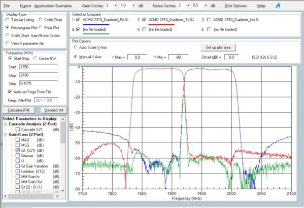
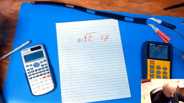
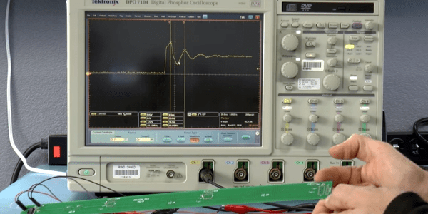
When is the speed of light not the speed of light? Of course, that’s a trick question. The speed of light may be constant, but just as sound travels at different speeds in different media, electronic signals move through transmission lines at a reduced speed. When you have a known cable, you can look up the velocity factor and use it to approximate the length of cable to have a given effective length. But what if you don’t know what kind of cable you have? [More Than Electronics] used a scope to measure it. You can see what he did in the video below.

For example, RG-8/U has a factor of 0.77. Even air isn’t exactly a factor of 1, although it is close enough that, in practice, we pretend that it is. If you wonder why it matters, consider stubs. Suppose you have a 300 MHz signal (handy because that’s 1 meter in wavelength; well, OK, pick 299.792 MHz if you prefer). If you have a quarter wavelength piece of coax shorted at one end, it will attenuate signals at 300 MHz. To understand why, picture the wave on the stub. If the close end of the stub is at 0 volts, then the other end — because it is a quarter wavelength away — must be at the maximum positive voltage or the minimum negative voltage. If either of the extremes is at the close end, then the far end must be at zero volts. That means the maximum current flows only when the signal is at 300 MHz.

Continue reading “Measuring An Unknown Velocity Factor”

Harvesting Electricity From High-Voltage Transmission Lines Using Fences

When you have a bunch of 230 kV transmission lines running over your property, why not use them for some scientific experiments? This is where the [Double M Innovations] YouTube channel comes into play, including a recent video where the idea of harvesting electricity from HV transmission lines using regular fences is put to an initial test.

The nearly final measurement by [Double M Innovations].
The nearly final voltage measurement by [Double M Innovations].
A rather hefty 88 µF, 1200 V capacitor, a full bridge rectifier, and 73 meters (240 feet) of coax cable to a spot underneath the aforementioned HV transmission lines. The cable was then put up at a height consistent with that of fencing at about 1.2 m (4 ft), making sure that no contact with the ground occurred anywhere. One end of the copper shield of the coax was connected to the full bridge rectifier, with the opposite AC side connected to a metal stake driven into the ground. From this the capacitor was being charged.

As for the results, they were rather concerning and flashy, with the 1000 VAC-rated multimeter going out of range on the AC side of the bridge rectifier, and the capacitor slowly charging up to 1000 V before the experiment was stopped.

Based on the capacity of the capacitor and the final measured voltage of 907 VDC, roughly 36.2 Joule would have been collected, giving some idea of the power one could collect from a few kilometers of fencing wire underneath such HV lines, and why you probably want to ground them if energy collecting is not your focus.

As for whether storing the power inductively coupled on fence wire can be legally used is probably something best discussed with your local energy company.

Continue reading “Harvesting Electricity From High-Voltage Transmission Lines Using Fences”

AppCAD Does Transmission Lines

Broadcom and Agilent are perhaps not household words in every household, but among those who work with RF, they are common enough names. An Agilent developer wrote AppCAD to help with common RF design computations and now works for Avago who bought Broadcom. But whoever’s branding is on it, you can download the tool from Broadcom or check out the latest beta version. Then watch [IMASI Guy’s] video below on how to use part of it.

What can it do? According to the website:

  • S-Parameter Analysis and Plotting
  • Active Circuit Bias Design
  • Cascade Noise and IP3 Analysis
  • Transmission Line Analysis
  • Signals and Systems
  • Complex Math Engineering Calculator

Continue reading “AppCAD Does Transmission Lines”

Finding RF Cable Impedance

At DC and low frequency, we can pretend wires are perfect conductors. At radio frequencies, though, there are many effects that you need to take into account for wires and cables. One of these is characteristic impedance. If you have a marked cable, you can look it up on the Internet, of course. But what if you don’t know what kind of wire it is? With help from [The Offset Volt], you can measure it as he shows in the video below.

This is one of those things that used to take exotic test equipment like an LCR bridge, but these days meters that measure inductance and capacitance are commonplace. The trick is simple: measure the capacitance and then short one end of the cable and measure the inductance.

Continue reading “Finding RF Cable Impedance”

Oliver Heaviside: Rags To Recognition, To Madness

Like any complex topic, electromagnetic theory has its own vocabulary. When speaking about dielectrics we may refer to their permittivity, and discussions on magnetic circuits might find terms like reluctance and inductance bandied about. At a more practical level, a ham radio operator might discuss the impedance of the coaxial cable used to send signals to an antenna that will then be bounced off the ionosphere for long-range communications.

It’s everyday stuff to most of us, but none of this vocabulary would exist if it hadn’t been for Oliver Heaviside, the brilliant but challenging self-taught British electrical engineer and researcher. He coined all these terms and many more in his life-long quest to understand the mysteries of the electromagnetic world, and gave us much of the theoretical basis for telecommunications.

Continue reading “Oliver Heaviside: Rags To Recognition, To Madness”

Long PCB Shows Effects Of Ludicrous Speed

Transmission lines can seem like magic. When you make use of them it seems strange that a piece of wire can block or pass certain frequencies. It is less common to use transmission lines with pulses and typically your circuit’s transmission line behavior isn’t all that significant. That is, until you have to move a signal a relatively long distance. [Robert Baruch] has been using a long PCB to test pulse behavior on a bus he’s working on. He actually has a few videos in this series that are worth watching.

What makes it interesting is that [Robert] has enough distance on the board to where light-speed effects show up. By using a very nice DPO7104 oscilloscope and a signal generator, he shows how the signal reflects on the line at various points, adding and subtracting from it. The measurements matched theory fairly closely. You shouldn’t expect them to match exactly because of small effects that occur randomly throughout the system.

Continue reading “Long PCB Shows Effects Of Ludicrous Speed”

Model Of A Transmission Line

Transmission lines are the kind of thing that seems to confuse beginners. After all, the fact that short-circuits can have infinite impedance and open-circuits can behave like a short is not intuitive at all!. That’s why we like [Tinselkoala]’s latest video that shows a nice model of a transmission line. It helps to understand the line as inductors and capacitors in series-parallel connection.

Any pair of wires used to transmit electrical power have tiny amounts of inductance and capacitance. This is not a problem with DC or low-frequency AC, but when the frequency is sufficiently high, weird things start to happen. The energy tends to escape as radio waves, and current reflects from discontinuities such as connectors and cable joints.  For this reason, transmission lines for high frequency signals use specialized construction to minimize those effects and reduce power losses.

[Tinselkoala] has built a model of a transmission line using coils and capacitors to simulate the inductance and capacitance of the line, with LED’s placed between the coils. He feeds the system with the signal generator with frequencies from 10 kHz to 1 MHz. In his words, they act as simple “visual voltmeters” to show the peaks and nodes of the standing waves of voltage in the line.

It is relatively simple to build your own version if you want to experiment with this fascinating subject. You will only need some magnet wire, capacitors, resistors and LED’s. If the subject sounds interesting to you,  here you can find an excellent introduction to transmission lines.

Continue reading “Model Of A Transmission Line”