Transmission lines are the kind of thing that seems to confuse beginners. After all, the fact that short-circuits can have infinite impedance and open-circuits can behave like a short is not intuitive at all!. That’s why we like [Tinselkoala]’s latest video that shows a nice model of a transmission line. It helps to understand the line as inductors and capacitors in series-parallel connection.
Any pair of wires used to transmit electrical power have tiny amounts of inductance and capacitance. This is not a problem with DC or low-frequency AC, but when the frequency is sufficiently high, weird things start to happen. The energy tends to escape as radio waves, and current reflects from discontinuities such as connectors and cable joints. For this reason, transmission lines for high frequency signals use specialized construction to minimize those effects and reduce power losses.
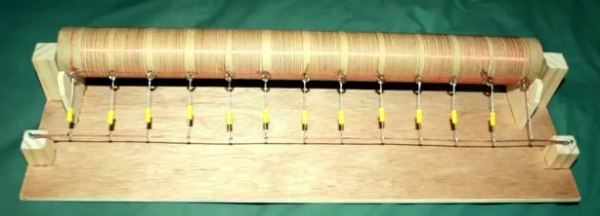
[Tinselkoala] has built a model of a transmission line using coils and capacitors to simulate the inductance and capacitance of the line, with LED’s placed between the coils. He feeds the system with the signal generator with frequencies from 10 kHz to 1 MHz. In his words, they act as simple “visual voltmeters” to show the peaks and nodes of the standing waves of voltage in the line.
It is relatively simple to build your own version if you want to experiment with this fascinating subject. You will only need some magnet wire, capacitors, resistors and LED’s. If the subject sounds interesting to you, here you can find an excellent introduction to transmission lines.
Continue reading “Model Of A Transmission Line” →