Auxiliary Display For Beat707 Works Via I2C

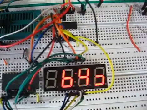
Bigtime is a simple way to create an auxiliary display for the Beat707 MIDI controller. The right half of the display shows the beat pattern that the drum machine is using, while the left half keeps track of the current measure.

Just a few components went into the extra hardware. A four-digit seven segment display is fed data from an ATtiny85. Since that microcontroller has only eight pins, a 595 shift register and CD4067 take care of translating serial data into the outputs necessary to light the display. The entire thing connects to the Beat707’s I2C bus, which means you don’t need to make hardware alterations to the original, and this leaves plenty of room for more addons.

The code package includes a Fritzing file, but for your convenience we’ve embedded a PNG of the hardware connections after the break. You’ll also find the demo video where [Guilherme] explains how this works.

Continue reading “Auxiliary Display For Beat707 Works Via I2C”

Purdue IEEE ROV


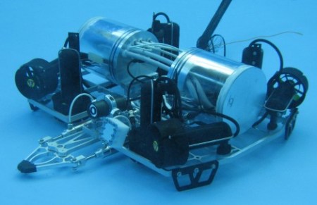
Purdue University’s IEEE branch participated in this year’s Marine Advanced Technology Education Center Competition, taking second place for the Hybris ROV seen above. The competition included several compulsory functions, including the ability to cap an underwater oil well, collect biological samples, and take water samples at depth.

What they came up with is a quick and agile watercraft that easily overcomes a lot of the hardware hangups that typically plague ROV builds. There are eight thrusters, four for vertical motion and the other four take care of horizontal movement. The gripper mechanism can be clearly seen on the front of the craft, with two cylindrical containers housing the electrical components.

Don’t miss out on the project definition page. Each challenge is discusses in detail, along with the team’s solution. We were impressed by the amount of information they have posted, including overview of each electrical component as well as design files and source code. If you want to see how the first run of the competition went, click through the break to find embedded video.

Continue reading “Purdue IEEE ROV”

Component Storage Roundup

It’s been suggested that the first self-replicating computer virus was a single IC that eventually expanded into multiple plastic component storage boxes. Organizing components by their values is a huge PITA as well. Here’s some solutions we’ve found:

Photo Boxes

[Mathew] sent in his organization scheme that uses 4×6 photo boxes. Better get those boxes while they’re hot – we can’t remember the last time we used film.

Use a binder

This instructables uses binders for storage. Good for passives, but unless someone can find anti-static bags for a binder, we’ll keep our ICs separate.

The only way to organize resistors

[Johannes] stores his resistors on a sheet of styrofoam. The grid has the first color band on the left side and the second color band on the top. Extremely, extremely clever. We’re wondering why we Radio Shack didn’t come up with this in the 70s. The grid could be laid out on a log scale, though.

If Susan is lazy, why does she do all the work?

[D.C. Boyce] hacked up a couple of lazy susans, built frames out of 2x4s and mounted plastic component drawers on them. The result is probably more space than we’ll ever need. To keep things simple, he wrote a database program to keep track of everything.

A Study In AVR Power Saving Techniques

amtel_avr

[Scott] found the iCufflinks from Adafruit Industries pretty interesting, but he thought that the stated run time of 24 hours was a bit short. He figured he could improve the product’s power consumption at least a little bit, to improve the overall battery life.

From their schematics, he placed an order for parts and built two identical iCufflink mock-ups side by side – one running their code and one running his. He took baseline current draw measurements, then got busy slimming down the cufflinks’ software. It had been 20 years since he touched assembly, and he has never written it for an AVR, but judging by his work he’s not rusty in the least.

He slowed the ATtiny’s clock down and tweaked a few other settings for a savings of 53μA, but the real improvements came via a fairly simple fix. The original code called for the processor to institute a counting loop to sleep, which he found to be very wasteful. Instead, he chose to put the processor in an idle state, using the chip’s watchdog timer to wake it when it was time to pulse the LED. The power savings from this change alone was a whopping 261μA!

When he was said and done, the changes save about 315μA of current draw, and should allow the cufflinks to run for up to 38 hours without swapping batteries. In [Scott’s] opinion, a nearly 60% improvement in battery life is pretty good for a day’s work, and we’re inclined to agree.

The Isostick

The Isostick, a Kickstarter project now in development, is meant to emulate an optical drive in the form of a USB stick.  Although there is nothing new with putting an iso file (optical disk image) on a USB stick, what is unique about this drive is that it fully emulates a drive without actually having to worry about drivers or extra programs.

When plugged in, a computer sees a flash drive and a virtual optical drive.  An excellent feature is that this disk can store multiple “iso” files and select them with a built in utility program. This could be invaluable for a technician or hacker since more than one CD or DVD is often needed to complete a task.

If fully developed, one could expect to attach this “drive” to your keychain and not have to worry about lugging an optical disk around anymore. Also, the activity light is programmable, which is a nice bonus.

Locking Notebook Enclosure

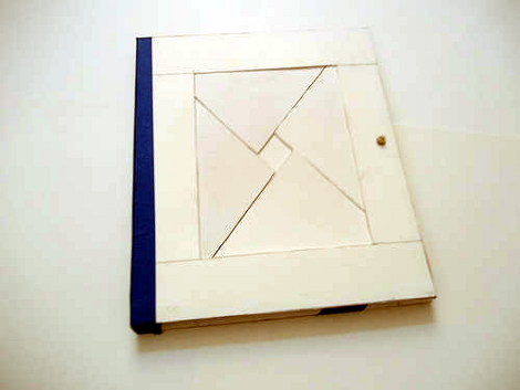
[Dombeef] made a locking enclosure for his sketchbook. The diamond seen in the center of the book is formed by the four sliding parts of the lock. Only with the proper movements will you get the cover open so you can plan your next hack.

He was inspired by this wooden version created by artist [Kagen Schaefer]. There were no tips about how the mechanism was made but a bit of deep thinking led [Dombeef] to discover the secret. Being the papercraft ninja that he is (he makes things like gyroscopes, strandbeests, and claws) this was created using cardstock as the parts. There is a wooden pin on the right that serves as the latch. Each of the four puzzle pieces moves around each other to free a slot from its hold on the notched latch.

There is a diagram showing the parts and their movements in the post linked above. [Dombeef] also mentioned an animated GIF that he promises to publish soon.

Update: Arduino Shift Register PWM Gets Speed Boost

Community collaboration is a great thing. Take the Arduino PWM library for shift registers. Some folks at the Arduino forum pitched in and helped [Elco] trim off a bunch of clock cycles by using the Rotate Over Carry instruction. Now he’s reduced the overhead per shift-register from 108 down to just 43. So far this doesn’t mean more possible outputs – 768 is still quite a lot – but does it means better precision when max outputs are used. This effectively doubles the brightness levels for 768 LEDs from 16 up to 32.

We’re at a loss for what to link to here. [Elco] has a new page for the library. There’s the original forums thread but we didn’t see much of interest there. We found some stuff in the comments of this Reddit post. And of course, if you have no idea what we’re talking about go back and read the original feature.