Plotting Pictures With Light

Flashing LEDs for a persistence of vision display are on bicycle wheels, alarm clocks, and even light painting sticks to draw images in the air. What if you wanted to plot an image in the air (translation) with a single LED? That’s what [acorv] did after taking a cue from a polar plotter.

Like the polar plotter and Drawbot, [acorv]’s build began with a pair of stepper motors and fishing line (translation). [acorv]’s brother upped the stakes a bit and suggested replacing the marker with an LED and taking long exposure photographs. Armed with a DSLR and a lot of patience, a few experimental pics were taken. To plot the image, the Lightbot flashes its LED as it goes across the plot area. The process of building an image pixel by pixel takes a while – eight minutes for this image – but the brothers were encouraged enough to take their rig outside.

After setting up the polar plotter between two tripods, [acorv] and his brother made this image in the dead of night. It’s an interesting spin on the POV LED builds we’ve seen before. Check out [acorv]’s Lightbot slowly drawing something after the break.

Continue reading “Plotting Pictures With Light”

Weekly Roundup 2/11/12


In case you have been on vacation, here is the best that we have had on our blog in the past week:

In first place is a post about [the University of Pennsylvania’s] quadcopter team. This time they have a group of twenty quadcopters flying in formation.

In second place is a post about a nice project by [Joel] where he converted an overhead projector into a TV projector by projecting through a LCD TV. He went all-out on this one by using a CNC machine to cut out a special holder for the LCD and the fans necessary to cool it.

Next up we have a post about a project where a 55 gallon plastic barrel is turned into a wind turbine. We’re not sure about how much power this would produce but it would probably be fun to play around with.

Following that is a follow up post about Printrbot, an inexpensive 3D printer which we previously posted about. It was a successful Kickstarter project a couple of months ago and now the design files have been released into the wild. Check it out!

Finally we finish off with a post about how to build a solid-state Tesla coil. It’s presented in an Instructable with 12 easy steps so that you too can feed your high-voltage addiction.

ElectroDroid – Your Android Electronic Reference App

Earlier this week, fellow Hack a Day-er [Mike Nathan] reviewed Adafruit’s new iPhone/iPad app Circuit Playground. The comments on [Mike]’s review turned to suggesting ElectroDroid as an alternative to Circuit Playground. Surprisingly,  Hack a Day authors actually pay attention to the comments, so I’ve decided to throw my hat into the ring and offer up my review of ElectroDroid. For purposes of full disclosure, I have to add that I paid the $2.59 donation for a copy of ElectroDroid without ads, and have had no contact with the developers.

Continue reading “ElectroDroid – Your Android Electronic Reference App”

POV Clock Spins Light Filter Instead Of LEDs

This hard-drive based POV clock is a treasure trove of great design choices. Now, we’ve seen a bunch of spinning clock builds. Several of the hard drive versions use slits cut in the platters to create a display by illuminating an LED behind those slits at just the right moment. This is a similar idea but [Jason Hotchkiss] ditched the platters all together and replaced them with a light filter. The filter disc has digits 0-9 as well as a colon (not seen above because the colons blink each second). As this disc spins, the Arduino compatible controller lights up LEDs in the eight digital positions to illuminate the correct number.

The filter is made from an etched copper-clad disc. This is a great choice because the fiberglass substrate is strong, light weight, translucent, and available. The filter idea also means you don’t need to get power or data to a spinning platform. [Jason] has also designed a very impressive controller board that is the same size as the footprint of the laptop hard drive he’s using. Check out the video after the break to see his description of what went into the hardware choices he arrived upon. Continue reading “POV Clock Spins Light Filter Instead Of LEDs”

Supercap Lights Your Way In Times Of Need

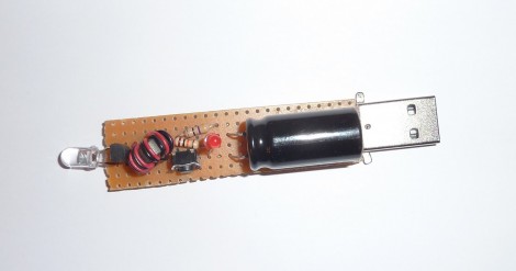
You won’t find [Antoine] stumbling around in the dark. He just finished working on this LED flashlight which draws power from a super-capacitor (translated). He realized that lighting a high-efficiency LED takes so little power that there are many benefits in play when deciding to move away from batteries. When compared to a super capacitor, batteries have a shorter life span, are heavier, and take up more space.

The biggest drawback of a super capacitor in this situation is the low voltage operation. The output will start at 2.7V and drop as the current is discharged. [Antoine] used one of our favorite simple circuits to overcome this issue, the Joule Thief. That circuit is commonly seen paired with an LED in order to boost input voltage to a usable level. That’s precisely what’s going on here.

The final hack in his circuit is the addition of that red LED which you can see in the middle of the board. This takes the place of a Zener diode and drops the charging voltage to a safe level. That indicator light will not come on until the cap is fully topped off. This way it tells you when the device is done charging.

Cockroft-Walton Multiplier Can Output Positive Or Negative Voltage

If you’ve already dipped your toes into high-voltage power supply pool you may be thirsty for a bit more knowledge. Here’s a neat illustration of how to build a voltage multiplier that can output a positive or negative supply. It is based on a design known as the Cockroft-Walton Multiplier. It’s the add-on housed in the plastic box seen in the image above. It uses diodes and capacitors in an orientation very common for generating high voltages. In fact, the same thing can be found in that high-voltage bulletin board. The place this differs is when it comes to connecting the multiplier to the PSU.

If you look closely you can see one red and one black banana plug jack poking out the end of the plastic container. There is also a pair of these on the other end. The multiplier has been designed so that reconfiguring the inputs and outputs changes how it works. Each jack has been labeled with one possible input and one output. Choose the desired output (DC+ or DC-) and then follow the labels for the rest of the connections.

What can you do with this setup? Check out the clip after the break that shows it powering a lifter.

Continue reading “Cockroft-Walton Multiplier Can Output Positive Or Negative Voltage”

JTAG Dongle Pushes Code To FPGA After Bootup

This gnarly beast has near-magical qualities. [Sprite_TM] patched it together as a dongle which attaches to a JTAG header (we’re fairly certain this is not a standard footprint for that interface though). He uses it to push code to an FPGA after that device boots. Why? Well, there’s several reason, but the most generic answer is that some boards will not boot unless there is a chain of trust that validates the code which will be running.

In this case, [Sprite_TM] is using a knock-off board he acquired from a Chinese supplier. It’s a hardware network terminal (thin client), and as you can see in the video after the break, it works just fine. But that’s pretty boring and he wanted to use it for his own purposes. When he plugs in the dongle and powers up the board the network terminal is nowhere to be found, replaced with the code to play Pac-Man as if were a full arcade cabinet.

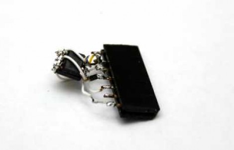
The dongle is simply a female DIL header, an ATtiny85, and a flash memory chip. The AVR has a software UART that speaks XSVF, the protocol used to push data to the FPGA. The data to be written is stored in the memory chip, and with that header in place reprogramming the AVR is just a matter of connecting an ISP programmer. Brilliant!

Continue reading “JTAG Dongle Pushes Code To FPGA After Bootup”