Weather Station Graphs History On Webpage

weather-station

Kudos go out to [Jose] for his work getting so many different components to talk to each other in this Arduino weather station that using a Raspberry Pi to display the data online.

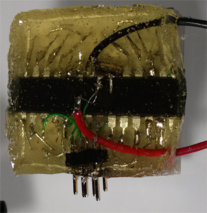
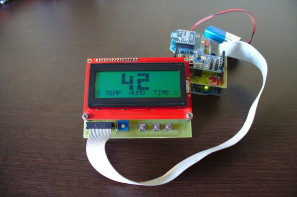
The components shown above make up the sensor package. There’s an Arduino with a custom shield that interfaces the barometric pressure sensor, real-time clock chip, a digital temperature sensor, and a humidity sensor. On top of that shield is an XBee shield that lets this push data back to the base station. [Jose] also rolled in an LCD character display and a few buttons so that the user may view weather data without heading to the web.

A Raspberry Pi board makes up the other half of the XBee pair. It harvests the incoming data from the radio module using a USB to Serial converter cable. You can see the data log on the webpage linked above. Just choose the “LIVE” menu option and click on “Daily” to get a better overview of humidity and pressure changes.

8×8 LED Matrix Pendant Sealed In A Block Of Epoxy

8x8-led-pendant

This is the back side of [Dmitry Grinberg’s] 8×8 LED matrix pendant. He had seen the other projects that used a 5×7 grid but wasn’t really satisfied with the figures that can be drawn in that confined area when each pixel has only the option of being on or off. His offering increases the drawing area and includes the ability to display each pixel at several different levels.

He’s using an ATmega328 microcontroller soldered directly to the pins on the back of the LED module. He mapped out the IO in his firmware to make the soldering as easy as possible. To protect the hardware he fashioned a mold around the edges of the LED package using duct tape. The tape held epoxy in place as it hardened, encasing the microcontroller and holding the power wires and ICSP header tightly.

After the break you can see about six seconds of the device in action. The four levels of brightness for each pixel really do make quite a difference!

Continue reading “8×8 LED Matrix Pendant Sealed In A Block Of Epoxy”

The PICnDuino Review

picnduino

For those of you that can’t make a decision between buying an Arduino and a PIC processor, [Brad] has come up with a novel solution, the PICnDuino. We’ve featured him before with his [Retroball] project, but this time Brad has been full funded on Kickstarter, and is pre-selling boards for delivery in March.

[HAD], specifically I, was fortunate enough to be sent one of the boards to try out early. I’ve worked with an Arduino before, but never a PIC processor, so read on to see if it was actually as easy as the tutorial video (at the end of the article) would have you believe it is to get started. Continue reading “The PICnDuino Review”

In-depth Look At An LVCD Board From A Saturn V Rocket

saturn-v-lvdc-board

Join [Fran] as she dons the hat of an electronics archaeologist when looking at this vintage circuit board from the space race. As part of her personal collection she somehow acquired a Launch Vehicle Digital Computer board for a Saturn V rocket. This particular unit was never used. But it would have been had the Apollo program continued.

[Fran] is enamored with this particular board because she believes it is the forerunner of modern digital circuit design and layout. Since routing circuit boards is part of what she does for a living you can see why this is important to her. Also, who isn’t excited by actual hardware from the space program? We’ve embedded two of her videos after the break. In the first she shows off the component to the camera and speaks briefly about it. But the second video has her heading to the dentist’s office for X-rays. The image above is a rotating X-ray machine, but it looks like the best imagery comes when a handheld gun is used. They get some great images of the traces, as well as the TTL components on the board itself.

Continue reading “In-depth Look At An LVCD Board From A Saturn V Rocket”

Unsigned Code Running On Windows RT

unsigned-code-on-windows-rt

A crack has been found in the armor of Windows RT. This subset of Windows 8 is designed to run on ARM processors. The payload listed in the image above allows you to run unsigned desktop applications on the OS.

We haven’t seen very much about the Windows RT package, so it’s nice to hear [Clrokr’s] thoughts on it. As far as he can tell the system has not been watered down from its Intel-aimed (x86) counterpart. Rather, RT seems to be a direct port with what is called “Code Integrity” mechanisms switched on. There is a kernel-level setting, barricaded behind UEFI’s Secure Boot, which determines the minimum software signing level allowed to run on the device. This is set to zero on a Windows 8 machine, but defaults to 8 on an ARM device. [Clrokr] uses a debugger to insert the code seen above into a DLL file in order to reset that minimum signing value to 0.

Do you have a project in mind for which this is useful? We’d love to hear about it in the comments!

[via Reddit]

Another Take On The Rear-window LED Marquee

re-window-led-display

This rear-window LED marquee will help let the driver behind you know when you’re planing to change lanes or make a turn. But it also includes the ability to send a message like “Back Off!”. [Robert Dunn] was inspired to undertake the project after seeing the one we featured back in October. We’d say his has a better chance of being street legal since it uses all red LEDs.

The marquee is a matrix of 480 LEDs, all hand soldered to form the nearly transparent 48×10 grid shown above. This is important to preserve visibility out the back window of his truck. It makes us wonder about the feasibility of using SMD instead of through hole components. That would certainly make it even less visible when not illuminated, but the assembly process would be much more difficult. That’s because the 5mm LED packages fit nicely in the grid of holes he drilled in some plywood which served as the jig during soldering. The presence of leads also made the soldering process manageable.

Power to an Arduino board is provided from the cigarette lighter adapter. A set of six shift registers drive the columns while the rows are controlled by a 4017 decade counter and some transistors. Check out the blinker test video after the break to get a look at what this can do while on the road.

Continue reading “Another Take On The Rear-window LED Marquee”

Garage Parking Monitor Guides You In Every Time

THEPARKINGSPOTTER2

The live Adafruit Show and Tell stream from last weekend featured this project put together by [Silent Jeff]. He’s called “Silent” because when it came time to present his project on the show his microphone wasn’t working. As you can see in the video after the break, [PT] and [Ladyada] worked together to explain the project (of which they had no prior knowledge) using a game of charades. This is one of the follow-up images he sent them which details his parking spotter project.

[Ladyada] compliments [Jeff] on the finished look of the device and we agree. Not only does this do a great job of letting a driver know if they have pulled far enough into the garage, but it’s finished appearance ensures it won’t ever look out-of-place. The two silver discs near the lower end of the box are the sensors of an ultrasonic rangefinder. You mount this box so that the sensor is measuring distance between itself and the bumper of your vehicle. As the distance decreases the LEDs change to let you know when to stop. Inside the case you’ll find a voltage regulator and single-chip running the Arduino bootloader. [Jeff] says this is just his second Arduino project and we hope that at this rate we’ll be looking for big things from him in the not too distant future!

This is basically the same idea as cars that use parking assist sensors in the bumper. It’s just attached to the building instead of to the vehicle itself.

Continue reading “Garage Parking Monitor Guides You In Every Time”