A Guitar From An Old Tin Box

omar-mos

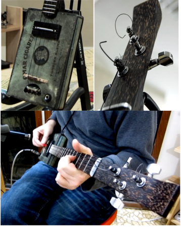
[Atdiy and Whisker], collectively known as  [The Tymkrs] have been busy honing their luthier skills. They’ve created a 10 part YouTube series about the construction of their new cigar box guitar. Instead of a cigar box though, they’ve substituted a 1920’s tin cigarette box. The Omar Cigarette company gave “Project Omar” it’s name. Like [Tymkrs] previous guitar, Omar is a three string affair. The neck was cut from Black Palm, which really shined when polished with a mixture of orange oil and beeswax. They also threw in a couple of new tricks on this build. Omar is an electric guitar, with a pickup custom wound  by [Bob Harrison]. Omar also has frets, which creates a whole new set of complications. Frets are generally installed by cutting slits in the guitar neck with a fret saw. Rather than buy a new tool, [Tymkrs] created a simple jig for their mini table saw. The jig held the guitar neck perpendicular with the saw blade. This made quick work of the many fret slits to be cut. Installed frets must also be dressed and leveled, which is a time-consuming process. 

The tin cigarette box also created a new set of problems. The thin tin proved to be a bit on the weak side when the strings were tightened down. A bit too much pressure on the box while playing would cause notes to bend, much like the tremolo or whammy bar on a standard electric guitar. [Tymkrs] were able to counteract this by adding bracing inside, and a couple of black palm braces to the back of the box.

Hum was also a problem. When [Tymkrs] first plugged in, they found they had more 60Hz mains hum than signal from their strings. Omar uses a classic single coil guitar pickup. Single coils will pick up noise from any magnetic field, including the field created by the studio electrical system. A humbucking pickup uses two coils to counteract this effect. Humbuckers also have a slightly different tone than single coils. [Tymkrs] wanted to stick with their single coil tone, so they counteracted the hum by raising the pickup closer to the strings. Higher pickups receive more signal from the strings, so this is basically a free signal to noise ratio improvement. They also grounded the entire tin box, along with Omar’s metal tail stock. The final build sounds great, as evidenced by the jam session toward the end of Video 10.

Continue reading “A Guitar From An Old Tin Box”

[Fran]’s LEDs, Nixies, And VFDs.

FRAN LED

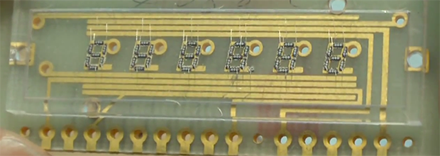
With a love of blinky and glowey things, [Fran] has collected a lot of electronic display devices over the years. Now she’s doing a few teardowns and tutorials on some of her (and our) favorite parts: LEDs and VFD and Nixie tubes

Perhaps it’s unsurprising that someone with hardware from a Saturn V flight computer also has a whole lot of vintage components, but we’re just surprised at how complete [Fran]’s collection is. She has one of the very first commercial LEDs ever made. It’s a very tiny red LED made by Monsanto (yes, that company) packaged in a very odd lead-and-cup package.

Also in her LED collection is a strange Western Electric part that’s green, but not the green you expect from an LED. This LED is more of an emerald color – not this color, but more like the green you get with a CMYK process. It would be really cool to see one of these put in a package with red, green, and blue LED, and could have some interesting applications considering the color space of an RGB LED.

Apart from her LEDs, [Fran] also has a huge collection of VFD and Nixie tubes. Despite the beliefs of eBay sellers, these two technologies are not the same: VFDs are true vacuum tubes with a phosphorescent coating and work something like a CRT turned inside out. Nixies, on the other hand, are filled with a gas (usually neon) that turns to plasma when current flows through one of the digits. [Fran] has a ton of VFDs and Nixies – mostly military surplus – and sent a few over to [Dave Jones] for him to fool around with.

It’s all very cool stuff and a great lead-in to what we hear [Fran] will be looking at next: electroluminescent displays found in the Apollo Guidance Computer.

Videos below.

Continue reading “[Fran]’s LEDs, Nixies, And VFDs.”

Recliner Sofa Given The Power Of The Pi

pi-sofa

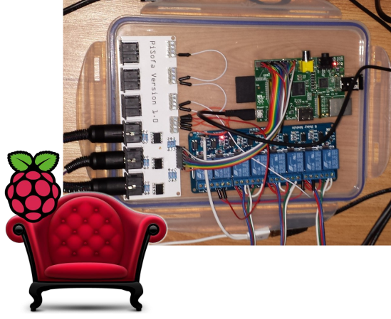
If you go to buy a sofa these days you’ll not only be greeted with the option of one or more reclining positions, but a fully modern unit comes with motorized reclining. That simply wasn’t convenient enough for [Nicki] and [Kevin] who wanted to control the feature from a smartphone rather than a physical interface (buttons) on the side of the furniture. What resulted is the PiSofa, a Raspberry Pi connected to the furniture’s electronics with the help of a relay board.

This is most certainly a hack, but no doubt one with a lot of finesse. Check out that white PCB. That’s right, it’s a factory spun board to keep things nice and neat. They went with one of our favorite tricks by housing everything inside of a food storage container. After some Ruby coding the Pi now has complete control of the sofa. We’re not overstating this. It literally is the only way to control it because the original buttons no longer work. But that’s okay, turns out not only does it work with their smartphones, but with a [Kevin’s] Pebble watch as well.

We can’t think of any past hacks that specifically targeted the couch. But here’s a hammock that you can drive down the street.

Building A Raspberry PI Digital Photo Frame

photoframe0103

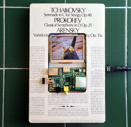
Digital photo frames aren’t very interesting on their own these days, but building one with a Raspberry Pi and strapping it with a bunch of useful features just might motivate you to check out this tutorial on building a ‘living’ digital photo frame.

This is [Samuel’s] first project with the Raspberry Pi, so he decided to build a digital photo frame that has the ability to download random pictures from his Flicker account and display them in a slideshow format. With all that extra IO on the Raspi, it was easy to incorporate a status LED and PIR sensor. When motion is detected by the PIR sensor, the photo frame is enabled; after 60 seconds of no movement, the photo frame is disabled by turning off the monitor port.

We love finding detailed write-ups like this because there is so much useful information in here like using the Flicker API, GPIO control, image handling, how to configure scripts to run on boot-up, and even some great troubleshooting code.  If you’d rather ditch the Raspi altogether and take things down a few levels, check out this PIC based 100% DIY digital picture frame.

Arcade Briefcase (the Briefcade)

20131109_134118

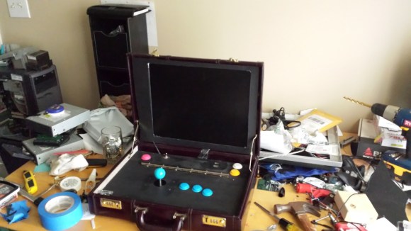
[Travis Reynolds] is part of an arcade club at work — the only problem? He’s the only one with an arcade machine, so they always end up at his place. So he decided to make his own portable, arcade briefcase to take to the office.

It all started with a quick trip to Goodwill where he found a beautiful maroon briefcase from the 80’s, for only $5! He then took apart a spare LCD monitor he had sitting around, and it worked incredibly well in his favor. He was able to reuse the LCD’s internal mounting brackets to secure it to the briefcase, and the video cables were just long enough to reach the Raspberry Pi.

The next problem he faced was the joystick height. He picked a Sanwa style joystick which is fairly small, but even that was too tall for the briefcase. So unfortunately, he needs to remove the ball of the joystick before closing the case. After testing out the proposed button layout, he cut a plywood mounting plate to hold everything in place. A bit of black spray paint later plus a power connector through the side of the case, and it’s complete!

He’s running Shea Silverman’s PiMame, which has an easy to use menu, quick setup, and great support. It’s an awesome project, and very well documented in case you’re itching to do something similar — I know we are!

Of course, if you have the space, a coffee table arcade machine is pretty sweet too…

[Thanks Brendan!]

Key Cutting With A CNC Mill

key2_zpsc260d079

Keys cost like what, $2 to copy at a locksmith? But where’s the fun in that? Here’s an easy way to cut your own keys using a CNC mill!

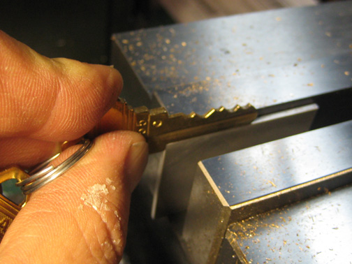
[Bolsterman] now “works” for a real estate company that rents out various properties. Whenever someone moves out, the locks need to be changed ASAP. They use Schlage locks, which can be re-keyed to any pin combination. New keys are typically cut with a punch or a key cutting machine — he actually had one years ago, but got rid of it. Not wanting to buy a new one for his new job at the real estate company, he decided to see how hard it would be to turn his small desktop CNC into his own personal key cutting machine.

All it took for [Bolsterman] to turn his mill into a key cutting machine was a 3/8th 90° countersink bit with the end ground to a flat approximately 0.055″ across (0.035″ is the width of a factory key, but a bit of leeway makes it easier to make the key). Then you simply zero the mill off of the shoulder of the key, and using the handy Schlage pin chart (included in the original link), cut the grooves!

To automate all of this, [Torrie Fischer] created a python script for generating the GCode  for keys based on [Bolsterman’s] technique — it’s hosted over at Noisebridge’s Wiki — check it out!

But if all that seems like too much effort, you could just print a new key instead…

PhotoTransistor Based Eye-Tracking

eyetrack

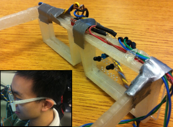
The applications of eye-tracking devices are endless, which is why we always get excited to see new techniques in measuring the absolute position of the human eye. Cornell students [Michael and John] took on an interesting approach for their final project and designed a phototransistor based eye-tracking system.

We can definitely see the potential of this project, but for their first prototype, the system relies on both eye-tracking and head movement to fully control a mouse pointer. An end-product design was in mind, so the system consists of both a pair of custom 3D printed glasses and a wireless receiver; thus avoiding the need to be tethered to the computer under control . The horizontal position of the mouse pointer is controlled via the infrared eye tracking mechanism, consisting of an Infrared LED positioned above the eye and two phototransistors located on each side of the eye. The measured analog data from the phototransistors determine the eye’s horizontal position. The vertical movement of the mouse pointer is controlled with the help of a 3-axis gyroscope mounted to the glasses. The effectiveness of a simple infrared LED/phototransistor to detect eye movement is impressive, because similar projects we’ve seen have been camera based. We understand how final project deadlines can be, so we hope [Michael and John] continue past the deadline with this one. It would be great to see if the absolute position (horizontal and vertical) of the eye can be tracked entirely with the phototransistor technique.

Continue reading “PhotoTransistor Based Eye-Tracking”