Micro-Scallop Robot

Nanobots Swim Like Scallops In Non-Newtonian Fluids

The idea of using nanobots to treat diseases has been around for years, though it has yet to be realized in any significant manner. Inspired by Purcell’s Scallop theorem, scientists from the Max Planck Institute for Intelligent Systems have created their own version . They designed a “micro-scallop” that could propel itself through non-Newtonian fluids, which is what most biological fluids happen to be.

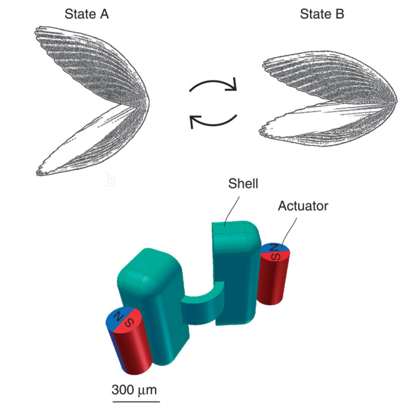
The scientists decided on constructing a relatively simple robot, one with two rigid “shells” and a flexible connecting hinge. They 3D-printed a negative mold of the structure and filled it with a polydimethylsiloxane (PDMS) solution mixed with fluorescent powder to enable detection. Once cured, the nanobot measured 800 microns wide by 300 microns thick. It’s worth noting that it did not have a motor. Once the mold was complete, two neodymium magnets were glued onto the outside of each shell. When a gradient-free external magnetic field was applied, the magnets make the nanobot’s shells open and close. These reciprocal movements resulted in its net propulsion through non-Newtonian media. The scientists also tested it in glycerol, an example of a Newtonian fluid. Confirming Purcell’s Scallop theorem, the nanobot did not move through the glycerol. They took videos of the nanobot in motion using a stereoscope, a digital camera with a colored-glass filter, and an ultraviolet LED to make the fluorescent nanobot detectable.

The scientists did not indicate any further studies regarding this design. Instead, they hope it will aid future researchers in designing nanobots that can swim through blood vessels and body fluids.  We don’t know how many years it will be before this becomes mainstream medical science, but we know this much: we will never look at scallops the same way again!

Continue reading “Nanobots Swim Like Scallops In Non-Newtonian Fluids”

Adding A Battery Gauge To A Project With Zero Parts

The typical way of doing a low battery detector is throwing a comparator in the circuit, setting it to measure a certain threshold voltage, and sending that signal off to a microcontroller or other circuit to notify someone the battery is going dead. [Josh] has a simpler way using an 8-bit AVR and zero other parts.

The chip [Josh] is using is the ATtiny84. The ADC in this chip is usually used to measure an unknown voltage against a reference voltage. The trick [Josh] is using is to do this in reverse: The internal 1.1 Volt reference voltage is measured against an unknown scale, namely the input voltage.

The value provided by the ADC on the chip will always be Vin times 1024 over the reference voltage. Since Vin will be 1.1 V in this case, the ADC value is known, it’s only a matter of doing some 6th grade algebra to determine the value of the input voltage.

[Josh] put together a small demonstration where the chip blinks out the number of volts its receiving from a bench power supply. By blinking a LED, it can blink out the current value of VCC as integers, but by using this technique you should be able to get a fairly fine-grained reading of what VCC actually is. Video below.

Continue reading “Adding A Battery Gauge To A Project With Zero Parts”

Ask Hackaday: Why Don’t We Have Flexible Displays Yet?

A few times a month we receive extremely well crafted crowdfunding campaigns in our tip line that make us doubt our sense of reality. While this article therefore isn’t a hack, we felt it would be a good place to start a discussion around OLED flexible displays.

As the dedicated Wikipedia article states flexible displays have been around for a few years already. In 2013, the Samsung Galaxy Round was unveiled as the world’s first mobile phone with a 5.7″ flexible display. The phone (and the screen) were curved in shape but the phone itself was solid. The same goes for the recent Samsung Gear S smart watch.

Yet for only $350 in a $50k goal crowdfunding campaign the Portal flexible wearable smartphone seems to have all the answers. It is scratch & shatter proof, water-resistant, flexible, includes a ‘Portal proprietary flexible battery’, the ‘Fastest multi-core CPU’, gyro, compass, barometer, Bluetooth 4.0, NFC, GPS…. Specifications are even subject to change to ensure the best available components… and it is 89% funded. As they mention,

building a smartphone or a tech company isn’t rocket science.

We also found a 70% funded €100k crowdfunding campaign for a watch bracelet (right click to translate) that will include GPS, Bluetooth, NFS (not a typo), a uSD card, a 4 lines LED screen and a battery for a few days autonomy… how surprising that no major manufacturer thought of that.

This leads us to the title of this post: why don’t we have truly flexible displays yet? We’ll let our readers discussion this point in the comments section below…

Talking Tactile 3D Prints

Cell biology professor [Mike] has created a way for blind students to decipher microscope slides using 3D prints and the magic of capacitive sensing. His write-up focuses on a slide showing the anaphase stage of mitosis in whitefish blastula, a popular choice for studying cell division. When a student touches a certain area of the print, the capacitive sensor triggers audio playback to tell them what they’re feeling.

[Mike] started by turning a 2D image of a cell into a 3D print. To do this, he made the image black and white, and then inverted the colors so that the 3D print’s topography will correspond correctly. The talking part is handled by an Arduino Duemilanove and a Spikenzie voice shield. The latter has a somewhat limited amount of space, but is more than adequate for the audio labels [Mike] made, which are all less than three seconds long.

A hard copy of the 2D file comes in handy for making sure the cap sensors are in the right places. To make those, [Mike] cut up some floor protector pads and covered the sticky side with copper tape. These are held on the 2D image with double-sided tape. The 3D print sits on top, separated by more furniture pads at the corners. He labeled this scientific sandwich model with a 3D printed Braille label that reads ‘anaphase’. [Mike] has made the referenced STL file along with a few others available at the National Institutes of Health’s 3D print exchange site.

Triple Sensor Mailbox Alert Really Delivers

Messing with the U.S. Mail is not something we generally recommend. But if you build your own mailbox like [Bob] did, you stand a much better chance of doing what you want without throwing up any flags.

Speaking of throwing up flags, one of the coolest parts of this project is the toy mailbox inside the house that monitors the activity of the real box. When there is mail waiting, the flag on the toy mailbox goes up. Once [Bob] retrieves the mail, the flag goes back down automatically. A magnet in the real box’s flag prevents false alarms on the toy box provided the Flag Raised On Outgoing protocol is followed. Best of all, he built in some distress handling: If the mailbox door is left hanging open or the battery is low, the toy mailbox waves its flag up and down.

So, where do the three sensors come in? A magnetic reed switch on the wall of the real mailbox pairs with a magnet in the flag. To determine whether the door is open, [Bob] initially used another magnetic reed switch on the underside of the box. This didn’t work well in wet weather, so he switched to a mechanical tilt sensor. An IR LED on the ceiling and a phototransistor on the floor of the box work together to detect the presence of mail.

[Bob]’s homebrew mailbox has a false back that hides a PIC 16F1825. When the door opens, the PIC wakes up, turns on a MOSFET, and checks the battery level. It waits two minutes for the mailman to do his job and then reads the flag state. After comparing the IR LED and phototransistor’s states, it sends a message to the toy mailbox indicating the presence or absence of mail.

The toy mailbox holds a modified receiver board and a servo to control its flag. [Bob] has made the code and schematics available on his site. Walk-through video is after the jump.

Continue reading “Triple Sensor Mailbox Alert Really Delivers”

Medical Tricorder Mark I

A handheld tricorder is as good a reason as any to start a project. The science-fiction-derived form factor provides an opportunity to work on a lot of different areas of hardware development like portable power, charging, communications between sensor and microcontroller. And of course you need a user interface so that the values being returned will have some meaning for the user.

[Marcus B] has done a great job with all of this in his first version of a medical tricorder. The current design hosts two sensors, one measures skin temperature using infrared, the other is a pulse sensor.

For us it’s not the number of sensors that makes something a “tricorder” but the ability of the device to use those sensors to make a diagnosis (or to give the user enough hints to come to their own conclusion). [Marcus] shares similar views and with that in mind has designed in a real-time clock and an SD card slot. These can be used to log sensor data over time which may then be able to suggest ailments based on a known set of common diagnosis parameters.

Looking at the image above you may be wondering which chip is the microcontroller. This build is actually a shield for an Arduino hiding underneath.

There’s a demonstration video after the break. And if you find this impressive you won’t want to miss the Open Source Science Tricorder which is one of the finalists for the 2014 Hackaday Prize.

Continue reading “Medical Tricorder Mark I”

The KIM-1 Computer Minified

The KIM-1 wasn’t the first microcomputer available to computer hobbyists and other electron aficionados, but it was the first one that was cheap. It was also exceedingly simple, with just a 6502 CPU, a little more than 1k of RAM, 2k of ROM, a hexadecimal keypad and a few seven-segment displays. Still, a lot of software was written for this machine, and one of these boards can be found in every computer history museum.

[Oscar] thought the KIM-1 was far too cool to be relegated to the history books so he made his own. It’s not a direct copy – this one uses an Arduino for the brains, only breaking out some buttons, a pair of four-digit seven-segment displays, and the I2C and SPI pins on the ‘duino. The KIM-1 is emulated by the Arduino, allowing for the same interface as an original connected up to an old teletype, and [Oscar] got his hands on the original code for Microchess and the first 6502 disassembler from [Woz] and [Baum].

[Oscar] put the schematics for his version of the KIM-1 up, and has the PCBs up on SeeedStudio. If you’re looking for an awesome replica of a vintage computer and a nice weekend project, here ‘ya go.