Controlling A Block Camera With An RC Transmitter

The world of drones and FPV remote-controlled aircraft is rapidly expanding, airframes are getting bigger, and the demand for even cooler AV gear is higher than ever. [elad] got his hands on a Sony block camera that is able to zoom in on a scene – great if you want to get close to the action while still flying a safe distance away. Controlling the zoom on these cameras is usually done through RS232, but [elad] made it work with an RC transmitter.

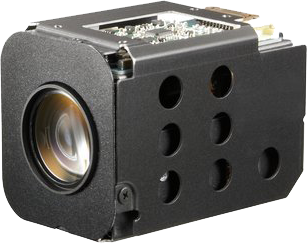
The camera [elad] is using is a Sony FCB-EX11D block camera with a standard SD resolution sensor. This camera has 10x optical zoom, making it a great solution to aerial surveillance, the only problem being the RS232 connection and the VISCA protocol. [elad] used an Arduino to listen in on the elevator channel from an RC receiver, translating that to something the camera will understand. The result is a controllable zoom on a camera that could easily take to the skies.

The entire camera package, with Arduino and electronics included, weighs in at about 100 grams. That’s about the same as a GoPro, and would fit perfectly on a camera gimbal. The only problem is getting a transmitter with enough channels or someone else to operate the camera while flying. Video below.

Continue reading “Controlling A Block Camera With An RC Transmitter”

A Custom Control Surface For Audio/Video Editing

Control surfaces (input devices with sliders, encoders, buttons, etc) are often used in audio and video editing, where they provide an easy way to control editing software. Unfortunately even small control surfaces are fairly expensive. To avoid shelling out for a commercial control surface, [Victor] developed his own custom control surface that sends standard MIDI commands which can be interpreted by nearly any DAW software.

[Victor]’s control surface includes several buttons, a display, and a rotary encoder. His firmware sends MIDI commands whenever a button is pressed or the rotary encoder is turned. [Victor] plans on adding menu functionality to the currently unused LCD display which will allow the user to change the scrubbing speed and other various settings.

One advantage of making your own control surface is that you can customize it to your own needs. [Victor] has posted a model of his 3d-printed enclosure and his source code on the project page so you can easily modify his design with any button configuration you might want.

Checking Email With The ESP8266

Ever so slowly, everyone’s favorite WiFi adapter is making its way into Internet-enabled projects. [jimeer01] created a device that reads the subject and sender lines from the latest email in his inbox and displays it on an LCD using the ESP8266 WiFi chip.

[jimeer] is using a ByPic for writing to the LCD and querying an inbox through an ESP8266 module. The ByPic is a board built around the BV_Basic firmware, stuffing a PIC microcontroller in an Arduino form factor and giving it a BASIC interpreter. Because this board isn’t ‘compile and flash’ like an Arduino, it’s perfectly suited for changing WiFi configurations and IMAP server credentials on the fly.

The device grabs the latest email in an inbox and displays the date, sender, and subject on the display. After scrolling through those lines, the PIC hits the ESP8266 to query the server again, grabbing the latest email, and repeating the whole process again, all without needing to connect the device to a computer. Video below.

Continue reading “Checking Email With The ESP8266”

Low-Voltage Tube Amp Is Great For Beginners

If you ever wanted to build your own tube amplifier but you were intimidated by working with high voltages, [Marcel]’s low-voltage tube amp design might spark your interest. The design operates with a B+ (plate) voltage of only 40v, making it less intimidating and dangerous than many other amps that operate over 300V. It’s also incredibly easy to build—the whole design uses only 11 components.

The amplifier is designed around the ECL82 tube, which includes both a triode and a pentode in one package. The ECL82 is practically an amplifier in a tube: it was designed for low-cost electronics like record players that needed to be as simple as possible. The triode in the ECL82 is used as a pre-amplifier for the incoming signal. The pentode is controlled with the pre-amplified signal and acts as a power amplifier.

[Marcel]’s amplifier also uses a PY88 tube rectifier instead of semiconductor diodes, making it an entirely silicon-free design. Although [Marcel] hasn’t posted up detailed build instructions yet, his simple schematic should be all you need to get started. If you want some more background information about tube amps but you don’t know where to start, check out our post on basic tube amp design from earlier this year.

Stereo Vision And Depth Mapping With Two Raspi Camera Modules

The Raspberry Pi has a port for a camera connector, allowing it to capture 1080p video and stream it to a network without having to deal with the craziness of webcams and the improbability of capturing 1080p video over USB. The Raspberry Pi compute module is a little more advanced; it breaks out two camera connectors, theoretically giving the Raspberry Pi stereo vision and depth mapping. [David Barker] put a compute module and two cameras together making this build a reality.

The use of stereo vision for computer vision and robotics research has been around much longer than other methods of depth mapping like a repurposed Kinect, but so far the hardware to do this has been a little hard to come by. You need two cameras, obviously, but the software techniques are well understood in the relevant literature.

[David] connected two cameras to a Pi compute module and implemented three different versions of the software techniques: one in Python and NumPy, running on an 3GHz x86 box, a version in C, running on x86 and the Pi’s ARM core, and another in assembler for the VideoCore on the Pi. Assembly is the way to go here – on the x86 platform, Python could do the parallax computations in 63 seconds, and C could manage it in 56 milliseconds. On the Pi, C took 1 second, and the VideoCore took 90 milliseconds. This translates to a frame rate of about 12FPS on the Pi, more than enough for some very, very interesting robotics work.

There are some better pictures of what this setup can do over on the Raspi blog. We couldn’t find a link to the software that made this possible, so if anyone has a link, drop it in the comments.

Hackaday’s 48-Hour Tokyo Speedrun

“The future is already here – it’s just not evenly distributed,” goes the clichéd [William Gibson] quote. Growing up on all the Cyberpunk literature and spending a more-than-healthy amount of time obsessing over [Fred Gallagher’s] Megatokyo series, I always imagined Japan to be at the very tail of this distribution. The place where the Future lives. Though it has been decades since the Bubble burst, and there’s no way this could still be the case, there was something romantic about believing it just might be. Thus, I opted for keeping the dream alive and never actually visited the place.

Not until a few weeks ago — [Bilke], one of our crazy sysadmin guys that keeps Hackaday.io alive, made me do it. He found these cheap tickets from LA, and the next thing you know – we were flying out for a 48-hours-in-Tokyo weekend. With no time to prepare, we reached out to [Akiba] from Freaklabs and [Emery] from Tokyo Hackerspace for some tips. By the time we landed, emails were waiting for us, with our full schedule completely worked out. It’s great to know that no matter where you are, there’s always a friendly local hacker willing to help.

Past the immigration, we took the JR Narita Express line into to the City that Friday evening. From there we grabbed a taxi because we couldn’t understand a word in katakana but then we hopped the JR Yamanote Metro line once we had figured things out. We checked out all the major places we had ever heard of (Shinjuku, Shibuya, Roppongi, Ginza…) because the jet lag was not letting us sleep anyway.

Sometime way past midnight, it hit me – Future Shock. But this was the kind I never expected…

Continue reading “Hackaday’s 48-Hour Tokyo Speedrun”

The Tale Of Two Wearable Game Boys

We’re well past the time when Halloween costume submissions stop hitting the tip line, but like ever year we’re expecting a few to trickle in until at least Thanksgiving. Remember, kids: documentation is the worst part of any project.

[Troy] sent us a link to his wearable Game Boy costume. It’s exactly what you think it is: an old-school brick Game Boy that [Troy] wore around to a few parties last weekend. This one has a twist, though. There’s a laptop in there, making this Game Boy playable.

The build started off as a large cardboard box [Troy] covered with a scaled-up image of everyone’s favorite use of AA batteries. The D-pad and buttons were printed out at a local hackerspace, secured to a piece of plywood, and connected to an Arduino Due. The screen, in all its green and black glory, was taken from an old netbook. It was a widescreen display, but with a bezel around the display the only way to tell it’s not original is from the backlight.

Loaded up with Pokemon Blue, the large-scale Game Boy works like it should, enthralling guests at wherever [Troy] ended up last Friday. It also looks like a rather quick build, and something we could easily put together when we remember it next October 30th.

[Troy] wasn’t the only person with this idea. A few hours before he sent in a link to his wearable Game Boy costume, [Shawn] sent in his completely unrelated but extremely similar project. It’s a wearable brick Game Boy, a bit bigger, playing Tetris instead of Pokemon.

[Shawn]’s build uses a cardboard box overlaid with a printout of a scaled-up Game Boy. Again, a laptop serves as the emulator and screen, input is handled by a ‘duino clone, and the buttons are slightly similar, but made out of cardboard.

Both are brilliant builds, adding a huge Game Boy to next year’s list of possible Halloween costume ideas. Videos of both below.

Continue reading “The Tale Of Two Wearable Game Boys”