Trinket Everyday Carry Contest Drawing #2 Results

We’ve held our second drawing for the Trinket Everyday Carry Contest. This week we used a Pro Trinket to pick the random winner. The winner is [mikeneiderhauser] with his project WorkoutAid!
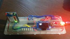
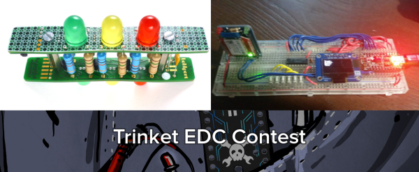
workoutaid[Mike] loves hitting the gym, but hates pulling out his phone or fumbling with his headphones to change songs during his routine. WorkoutAid is designed to fix this problem. It’s essentially a Bluetooth media display and remote. Track metadata will be displayed on a 128×64 OLED. 6 buttons will allow the user to change tracks, volume, or perform other functions. The whole device will communicate with a custom Android application through an RN42X Bluetooth radio.

trinket-prize-cordwoodWe hope [Mike] enjoys his new Cordwood Puzzle from The Hackaday Store. No jigsaws here, cordwood is a puzzle that involves solder! It’s built using the cordwood assembly technique which was popular in the 1950’s and 1960s. We’re not kidding about it being a puzzle either – there are no instructions for this kit! [Mike] will know he’s got it right when all 3 LEDs light up.
buspirate2

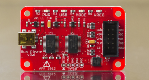
If you didn’t win this week, don’t worry, there are still three more chances to win a random drawing! Our next drawing will be on 12/16/2014 at 9pm EST. The prize will be the ever handy Bus Pirate V3.6. To be eligible you need to submit your project as an official entry and publish at least one project log during the week.

The deadline for the big contest is January 2, 2014! More than 60 projects are entered so far, but only the top 50 will receive custom t-shirts. The top three projects will win some seriously awesome prizes, including a Rigol DS1054Z Oscilloscope, a Fluke 179 meter, and a Hakko/Panavise soldering bundle.

So what are you waiting for? Get off the couch and get hacking!

Digging Into The APA102 Serial LED Protocol

[Tim] got his hands on some APA102 RGB LEDs, which are similar in function to the common WS2812 addressable LEDs seen in many projects we’ve featured. The advantage of APA102 LEDs is that they don’t have the strict timing requirements of the WS2812. These LEDs are controlled with a SPI bus that can be clocked at any arbitrary rate, making them easy to use with pretty much any microcontroller or embedded system.

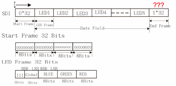
After working with the LEDs, [Tim] discovered that the LEDs function a bit differently than the datasheet led him to believe. [Tim] controlled a strand of APA102 LEDs with an ATtiny85 and connected a logic analyzer between some of the LEDs. He discovered that the clock signal of the SPI interface isn’t just passed through each LED, it actually looks like it’s inverted on the output. After some investigation, [Tim] found that the clock signal is delayed by a half period (which looks like an inversion) before it’s passed to the next LED. This gives the next LED in the strand enough time for data on the data line to become valid before latching it in.

Since the clock is delayed, [Tim] discovered that additional bits must be clocked as an “end frame” to generate clock signals which propagate the remaining data to the end of the strand. Although the datasheet specifies a 32-bit end frame, this only works for strings of up to 64 LEDs. More bits must be added to the end frame for longer strands, which the datasheet doesn’t even mention. Check out [Tim]’s post for more information, where he walks you through his logic analysis of the APA102 LEDs.

12 Mbps Communication Between A PC And MCU

The world of hobby electronics have only started putting USB in projects for the last few years, and right now, pushing 1.5 Mbps down a USB port is good enough for most cases. This isn’t true for all cases; that’s a terrible data rate, really, and to get the most out of a USB connection, you can at least move up to USB Full Speed and 12 Mbps.

[Linas] is using the STM32F4 microcontroller for this example, an extremely large and very capable chip. [Linas] is using FTDI’s FT2232D USB UART to send data from an SPI port over USB. This chip does support 12 Mbps, but only after a few additions; an external EEPROM must be connected to the FTDI chip to provide a USB 2.0 device descriptor, otherwise the connection between the microcontroller and a computer is limited to 1.5 Mbps. Even using the USB on the STM32 would be a bottleneck in this case; [Linas] is moving data out of the processor using only the DMA controller – using the USB on the STM32 would eat up processor cycles in the microcontroller.

Thanks to the DMA controller inside the STM32, the microcontroller is capable of sending and receiving data through SPI at the same time. The STM32 is capable of reading and writing to the Tx and Rx buffer at the same time, but the computer is only capable of half-duplex operation – it can only read or write at any one time. [Linas] is setting up the DMA controller on the STM32 as a circular mode, putting everything in the buffer into the FTDI chip, and reading everything sent from the computer back into the STM32’s memory. After counting off the correct number of packets. the controller resets everything, moves the circular buffer back to the beginning, and starts the whole process over again.

The circuit was prototyped with an STM Discovery board. With Labview, [Linas] can see the bits coming out of the microcontroller, and send some bits back to the micro over USB. [Linas] has an extraordinarily detailed video tutorial on this project. You can check that out below.

Continue reading “12 Mbps Communication Between A PC And MCU”

A Calculator With Free Software And Open Hardware

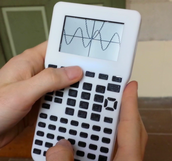
We’re fond of open source things here. Whether it’s 3D printers, circuit modeling software, or a global network of satellite base stations, the more open it is the more it improves the world around us. [Pierre Parent] and [Ael Gain] have certainly taken these values to heart with their open handheld graphing calculator.

While the duo isn’t giving away the calculators themselves, they are releasing all of the hardware designs so that anyone can build this calculator. It’s based on a imx233 processor because this chip (and most everything else about this calculator) is easy to source and easy to use. That, and there is a lot of documentation on it that is in the public domain. All of the designs, including the circuit board and CAD files for the case, are available to anyone who is curious, or wants to build their own.

The software on the calculator (and the software that was used to design the calculator) is all free software too. The calculator runs Linux (of course) and a free TI simulator environment in the hopes of easing the transition of anyone who grew up using TI’s graphing calculators. The project is still in a prototype phase, but it looks very promising. Even though the calculator can already run Pokemon, maybe one day it will even be able to run Super Smash Bros as well!

Retrotechtacular: Supersonic Transport Initiatives

In the early days of PBS member station WGBH-Boston, they in conjunction with MIT produced a program called Science Reporter. The program’s aim was explaining modern technological advances to a wide audience through the use of interviews and demonstrations. This week, we have a 1966 episode called “Ticket Through the Sound Barrier”, which outlines the then-current state of supersonic transport (SST) initiatives being undertaken by NASA.

MIT reporter and basso profondo [John Fitch] opens the program at NASA’s Ames research center. Here, he outlines the three major considerations of the SST initiative. First, the aluminium typically used in subsonic aircraft fuselage cannot withstand the extreme temperatures caused by air friction at supersonic speeds. Although the Aérospatiale-BAC Concorde was skinned in aluminium, it was limited to Mach 2.02 because of heating issues. In place of aluminium, a titanium alloy with a melting point of 3,000°F is being developed and tested.

Continue reading “Retrotechtacular: Supersonic Transport Initiatives”

Scope Noob: Microcontroller Quirks With DDS

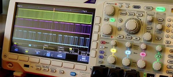
In this installment of Scope Noob I’m working with Direct Digital Synthesis using a microcontroller. I was pleasantly surprised by some of the quirks which I discovered during this process. Most notably, I had a chance to look at errant triggers solved by using holdoff and a few timing peculiarities introduced by my use of the microcontroller. Here’s a video synopsis but I’ll cover everything in-depth after the break.

Continue reading “Scope Noob: Microcontroller Quirks With DDS”

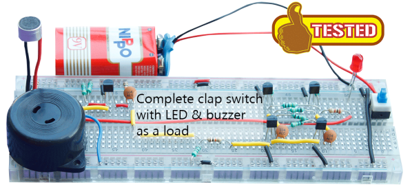
Clap On! A Breadboard

The Clapper™ is a miracle of the 1980s, turning lights and TVs on and off with the simple clap of the hands, and engraving itself into the collective human unconsciousness with a little jingle that implores – nay, commands – you to Clap On! and Clap Off! [Rutuvij] and [Ayush] bought a clap switch kit, but like so many kits, this one was impossible to understand; building the circuit was out of the question, let alone understanding the circuit. To help [Rutuvij] and [Ayush] out, [Rafale] made his own version of the circuit, and figured out a way to explain how the circuit works.

While not the most important component, the most obvious component inside a Clapper is a microphone. [Rafale] is using a small electret microphone connected to an amplifier block, in this case a single transistor.

The signal from the microphone is then sent to the part of the circuit that will turn a load on and off. For this, a bistable multivibrator was used, or as it’s called in the world of digital logic and Minecraft circuits, an S-R flip-flop. This flip-flop needs two inputs; one to store the value and another to erase the stored value. For that, it’s two more transistors. The first time the circuit senses a clap, it stores the value in the flip-flop. The next time a clap is sensed, the circuit is reset.

Output is as simple as a LED and a buzzer, but once you have that, connecting a relay is a piece of cake. That’s the complete circuit of a clapper using five transistors, something that just can’t be done with other builds centered around a 555 timer chip.