OSWatch, An Open Source Watch

If you are a soldering ninja with a flair for working with tiny parts and modules, check out the Open Source Watch a.k.a. OSWatch built by [Jonathan Cook]. His goals when starting out the project were to make it Arduino compatible, have enough memory for future applications, last a full day on one charge, use BLE as Central or Peripheral and be small in size. With some ingenuity, 3d printing and hacker skills, he was able to accomplish all of that.

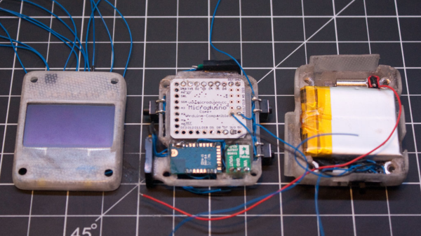
OSWatch is still a work in progress and with detailed build instructions available, it is open for others to dig in and create their own versions with modifications – you just need to bring in a lot of patience to the build. The watch is built around a Microdunio Core+ board, an OLED screen, BLE112A module, Vibration motor, a couple of LEDs and Buttons, and a bunch of other parts. Take a look at the schematics here. The watch requires a 3V3, 8MHz version of the Microdunio Core+ (to ensure lower power consumption), and if that isn’t readily available, [Jonathan]  shows how to modify a 5V, 16MHz version.

Continue reading “OSWatch, An Open Source Watch”

FIRST Robotics Gives Us Hope In The Next Generation Of Hackers

A top scoring team in FIRST Robotics shows off just what some high-school students are capable of. Called the Simbot SideSwipe, their 2015 robot is a slick piece of mechatronic genius, which according to our tipster was built in just six weeks by the students.

The robot is essentially a remote controlled palletizing forklift, capable of collecting and stacking six recycling totes, and a green bin. It’s an impressive combination of mechanical control and fabrication — though it is worth noting, these bots are remote controlled — not autonomous.

To encourage learning, the team has posted their engineering report, and even the CAD model online. They obviously had quite a bit of funding judging by their component selection, but regardless, we’re seriously impressed with both the design and execution of manufacturing their robot — especially if it was really built in just six weeks. Just take a look at the following videos:

Continue reading “FIRST Robotics Gives Us Hope In The Next Generation Of Hackers”

Decoupling Lego Trains Automatically

Lego train sets were introduced almost 50 years ago, and since then, one thing has been constant: the trains connected with magnets. While this is a supremely simple means of connecting locomotives to rolling stock, there is one big disadvantage. Building decouplers – devices that will separate one car from another – is difficult.

Now, with a clever combination of racks, gears, and wedges, trains can disassemble themselves. They can even do it with an Arduino.

wedgeThis decoupler works by effectively wedging cars apart from each other. With a motor from an old Lego Technic set, a few gears, shafts, and a rack, a device can be constructed that fits between the rails of a track that raises into the undercarriage of rolling stock.

Because this rolling stock is moved around with a locomotive, all that’s needed to separate two halves of a train is to move the locomotive forward. Yes, it does mean that the connection with the weakest magnet is disengaged – not necessarily the connection you want to decouple. However, with only one car and a locomotive, there’s only one connection to break. Simple enough.

This Lego decoupler can be further improved with an Arduino, a few ultrasonic sensors, and an IR detector to make a fully automatic decoupling siding for a Lego train layout. You can see all this below operating with a full state machine that perpetually switches rolling stock behind a locomotive.

A great use for Legos.

Continue reading “Decoupling Lego Trains Automatically”

ARM-Based Gesture Remote Control

When we wave our hands at the TV, it doesn’t do anything. You can change that, though, with an ARM processor and a handful of sensors. You can see a video of the project in action below. [Samuele Jackson], [Tue Tran], and [Carden Bagwell] used a gesture sensor, a SONAR sensor, an IR LED, and an IR receiver along with an mBed-enabled ARM processor to do the job.

The receiver allows the device to load IR commands from an existing remote so that the gesture remote will work with most setups. The mBed libraries handle communication with the sensors and the universal remote function. It also provides a simple real-time operating system. That leaves just some simple logic in main.cpp, which is under 250 lines of source code.

Continue reading “ARM-Based Gesture Remote Control”

Turning A Pi Into A PDP

There’s no better way to learn how to program a computer than assembly, and there’s no better way to do assembly than with a bunch of blinkenlights and switches. Therefore, the best way to learn programming is with a PDP-11. It’s a shame these machines are locked up in museums and the garages of very cool people, but you can build your own PDP-11 with a Raspberry Pi and just a few extra components.

[jonatron] built his own simulated version of the PDP-11 with a lot of LEDs, a ton of switches, and a few 16-bit serial to parallel ICs. Of course the coolest part of any blinkenlight simulator are the front panel graphics, and here [jonatron] didn’t skimp. He put those switches and LEDs on a piece of laser cut acrylic with a handsome PDP11 decal. The software comes with a load of compiler warnings and doesn’t run anything except for very simple machine code programs. That’s really all you can do with a bunch of toggle switches and lights, though.

If this project looks familiar, your memory does not deceive you. The PiDP-8/I was an entry in this year’s Hackaday Prize and ended up being one of the top projects in the Best Product category. We ran into [Oscar], the creator of the PiDP-8, a few times this year. The most recent was at the Hackaday SuperConferece where he gave a talk. He’s currently working on a replica of the king of PDPs, the PDP-11/70.

Video below.

Continue reading “Turning A Pi Into A PDP”

Piezoelectric Transformers Are A Thing, Have You Used One?

Cheap piezo buzzers are everywhere. They’re so cheap that they can be used in novelty birthday cards. Applying an alternating voltage across a piezo crystal makes it expand and contract, and fixing this crystal to a metal disk gives the piezo speaker its characteristic tinny sound that is anything but pleasant.

The piezoelectric effect works the other way too, and piezo elements are very useful as vibration sensors. Simply put one of your voltmeter leads on each of the piezo element’s wires and touch the element with your hand or knock it against your bench. You should see a voltage spike on your voltmeter which will change in magnitude with the amount of force you use when touching the element.

This ability to change shape when a voltage is applied and to create a voltage when they’re deformed is the basis of the piezoelectric transformer (PZT). While searching for a high voltage/low current transformer, Hackaday reader [Josh] was surprised to find a piezoelectric solution. He didn’t say whether he decided to use a PZT in his project but he did link us to a decent PDF on the subject.

piezo_transformerIn a PZT, two piezo elements sit next to each other. The primary is made up of multiple thin layers that expand horizontally and press on a single secondary piezo element. The more and the thinner the primary layers, the more force is exerted on the secondary, and the more voltage it develops. There are a few equations involved which you can check out in the PDF linked above that go over this concept in painful detail if you’re into that sort of thing.

If you have never played with piezo element you should add one to your next parts order. They are cheap and easy to experiment with. We have seen piezo elements used in DIY speakers, sonar projects, and even as the sensor for an atomic force microscope, but we have yet to see a piezoelectric transformer in a hack. Surely someone has used one in a project they worked on, leave us a link in the comments if you’re the person we’re talking about.

Raspberry Pi Communication Via LASER

[Nick Touran] wanted to make two Raspberry Pi’s communicate wirelessly. There are lots of options, but [Nick] used a LASER and a photoresistor, along with Morse code. If you don’t find Morse code fancy enough, you could always refer to it as OOK (on/off keying). The circuit uses a common LASER module and an ordinary photoresistor that varies in resistance based on light. A resistor forms a voltage divider with the photoresistor and an external A/D reads the resulting voltage.

The circuit works, but we couldn’t help but notice a few items. Not all photoresistors are as sensitive to the same light wavelengths, so for the maximum range you’d want to pick a particular photoresistor.  While the analog to digital converter is certainly workable, we couldn’t help but wonder if you couldn’t set up the divider to use the inherent threshold of the Raspberry Pi’s input pins for a simpler circuit. Of course, if you used the same technique with an Arduino, you could use the built-in A/D converter, and the A/D converter is probably easier to get working.

Continue reading “Raspberry Pi Communication Via LASER”