Wireless Water Meter Monitor Watches Waste

It’s no secret that hackers like to measure things. Good numbers lead to good decisions, like when to kick your wastrel teenager out of a luxuriously lengthy shower. Hence the creation of this wireless Arduino-based water meter interface.

We’ll stipulate that “wireless” is a bit of a stretch. Creator [David Schneider] chose to split the system into two parts – a magnetometer and an Arduino to sense impulses from the water company meter, and a Raspberry Pi to serve the web interface. The water meter is at the street rather than in his house, so the sensor is wired to the Pi with some telephone cable. But from there the system is wireless.

[David] goes into some good detail on the sensing problem he faced, which relies on detecting the varying magnetic field due to the spinny-bits inside the flowmeter and cleaning up the signal with the Arduino; he also addresses aliasing errors that occur when flow rate approaches the sampling rate of the magnetometer.

We like the fact that there’s a lot of potential to leverage this technique to monitor other processes with rotating magnetic fields. And like this optically coupled gas-meter monitor, it’s not invasive of the utility’s equipment either, which is a plus.

[via reddit]

Hacking Old Ethernet Gear

Have you ever wanted a pocket-sized device that could tell you if a network jack was live or not? [TanzerGuy] did and he hacked a piece of old networking gear to do the job.

Today when you think of Ethernet, you probably think of CAT-5 cable or something similar. But it hasn’t always been like that. In the early days of Ethernet networking, an Ethernet cable was a big piece of coax. A media attachment unit (MAU) clamped to the cable and then connected to an attachment unit interface (AUI) that resided in the actual network card. Later standards used thinner coax that attached to the card using a Tee connector, but even these are rare today.

Continue reading “Hacking Old Ethernet Gear”

Sudden Death Night Light Sounds Scary, Is Sweet

We have to admit that we were mislead by the title “Sudden Death: Wall Sign + Night Light”. This naturally conjured up images of deadly night lights, but the truth turned out to be a lot less fatal: [Smerfj] had two weeks to make a present for a friend’s wedding. The project was either a go or a no-go depending on the deadline — that sort of sudden death. But as we all know, deadlines have a way of bringing the motivation out of us that’s not always bad.

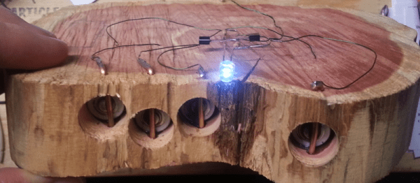
The night light in question is a bunch of hand-made circuits, each stuffed into a wooden slice with a letter burned on the face, spelling out [Smerfj]’s friend’s name. But to really appreciate it, you have to dig through the build details.

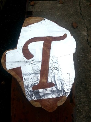
55461447189465844We didn’t know how to burn precise lettering into wood. [Smerfj] covered the wood in metal foil tape, then cut the letters out of the foil. Now applying the torch blackens only the part of the logs that have tape removed. Slick.

To get accurate lettering cut into the aluminum tape, [Smerfj] made an impromptu projector out of a cell phone taped to a chandelier (approximately a point light source) and a stencil suspended somewhere between the chandelier and the wood target. Naturally, this is best done in a darkened room under tight deadline pressure.

The battery holders are fantastic. Springs from commercial battery holders were soldered to enamel wire and placed in holes drilled just the width of AA batteries. With the length of the battery taken into account, channels were drilled into the wood and copper wires jammed through, holding the batteries in place, and providing the other electrical contact. Brilliant.

And finally, the free-form night light circuits are great. Fine-tuned to draw the minimum current, they’re adjusted to the specific LEDs and phototransistors that [Smerfj] had on hand. Bespoke free-form electronics in hand-blackened wood. That’s a nice gift.

Now [Smerfj] just needs nice packaging to present them in. We’re thinking DIY laser-cut boxes with interior lighting, naturally.

A Sound And LED-tastic Tricycle Shopping Cart

What do you get when you take a massive number of LEDs and combine them with a shopping cart and a bicycle? An awesome rave-mobile created by [kramerr]. He’s even taking it one step further by making the electronics solar powered.

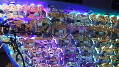
[Kramerr] controls the LEDs with multiple WS2803 LED drivers. Three PIC18F4550s control the WS2803s over SPI. He devised a neat way of exciting the LEDs from music by using a pair of graphic equalizer display filter chips, MSGEQ7s, to drive the PICs to create patterns. A USB input also allows the PICs to display song titles or other information.

leds and boards

The mechanical design is as impressive as the electronics. The rear half of a bicycle is welded to the frame of the shopping cart with the cart’s handle used for steering. The shopping cart’s rear wheels are replaced by small bicycle wheels.

But [Kramerr] wasn’t done. He built his own solar panel since he couldn’t find one to fit the size requirements. The panel consists of 26 cells connected in series to provide 1A at 13V on a sunny day. A solar charge controller keeps a standard 12v lead acid battery ready to power the tricycle cart.

And there is still more! There is a sound system driven by a Raspberry Pi. The Pi also drives the USB inputs when [Krameer] wants to display song titles or artists instead of the audio patterns.

There are at least four hacks in this project each worthy of applause. [Karmeer] deserves an ovation for doing all of them in one project. If you are looking for less bling and less pedaling may we direct you to this powered, riding shopping cart.

Some rave music and lights via video after the break.

Continue reading “A Sound And LED-tastic Tricycle Shopping Cart”

Light Up Your Day With This LED Clock

We love clocks, and [Chris] got our attention with the internet enabled Light Clock. Time is displayed via RGB LED strip in a number of different ways around a 3D printed white disk. All the modes are based on two selectable colors to indicate hours and minutes, either in a gradient fashion or a hard stop.

Light is provided by a 144 LED neopixel strip and is powered by a beefy 4 amp 5 volt power supply, which also powers the controller. Brains are provided by a ESP8266 powered NodeMCU-12E board, and software is written using ESP8266 for Arduino core.

Being a WiFi enabled micro controller it is a simple matter of connecting to the clock using WiFi and using the embedded web pages to select your local timezone, color palette, and display mode. The correct time is set by network and will never be wrong. While there is a Kickstarter for selling the finished project, instructions and software are provided for making your own if you wish.

Join us after the break for the promotional Kickstarter and demonstration video

Continue reading “Light Up Your Day With This LED Clock”

Experiences In Developing An Electronics Kit

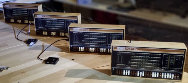
This year’s Hackaday Prize included a category for the Best Product, and there is perhaps no project that has inspired more people to throw money at their computer screens than [Oscar Vermeulen]’s PiDP-8/I. It’s a replica of the PDP-8/I from 1968. Instead of discrete electronics driving the blinkenlights and switches on the front of this computer, [Oscar]’s version uses a Raspberry Pi and the incredible SIMH emulator for dozens of old mainframes and minicomputers. It is, for all intents and purposes, a miniaturized version of a 50 year old computer that will fit on your desk and is powered by a phone charger.

Check out the video of [Oscar]’s talk below then join us after the break for more discussion of his work.

Continue reading “Experiences In Developing An Electronics Kit”

Swapping GPIO Pins On The Pi Zero For Audio

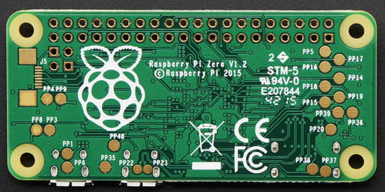
The new Raspberry Pi Zero is generating a lot of discussion, especially along the lines of “why didn’t they include…?” One specific complaint has been that audio is only available through the HDMI port. That’s not entirely true as pointed out by Lady Ada over at Adafruit.

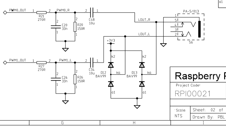
Something to remember about the entire Pi family is the pins on the Broadcom processors are multipurpose. Does it increase the confusion or the capabilities? Take your pick. But the key benefit is that different pins can handle the same purpose. For audio the Greater Than Zero Pis (GTZPi) use PWM0_OUT and PWM1_OUT on the processor’s GPIO pins 40 and 45. On the GRZPis these feed a diode, resistor and capacitor network that ends at the audio output jack. They don’t appear on the GPIO connector so cannot be used on the Zero.

The multi-pin, multi-purpose capability of the Broadcom processor allows you to switch PWM0_OUT to GPIO 18 and PWM1_OUT to GPIO 13 or 19. Add the network from the Adafruit note, or check this schematic from the Raspberry Pi site – look at the lower right on the second page.

raspberry_pi_audiofilter

While you’re checking out the audio hack at Adafruit, read through the entirety of Introducing the Raspberry Pi Zero. Lady Ada provides a great description of the Zero and what is needed to start using it.

If you’re looking for Zero hacking ideas you might check the comments in our announcement about the Zero or article on the first hack we received. There is a lot of grist for the hacking mill in them.