Reverse Engineering Galaga To Fix The No-Fire Cheat

We didn’t know there was a cheat to Galaga, but [Chris Cantrell] did. And so he did what any curious hacker would do — reverse-engineer the game to diagnose and eventually fix the bug.

Spoilers ahoy! Go read the website first if you’d like to follow [Chris]’s reversing efforts in the order that they actually happened.

The glitch is triggered by first killing most of the bees. When only six are left, they go into a second pattern where they swoop across the screen and wrap around the edges. While swooping, sometimes the bees will fire a shot when they’re at coordinates with X=0. Now two facts: there’s a maximum of eight missiles on the screen at any given time, and the position X=0 was reserved by the software to hide sprites that don’t need updating.

The end result is that eight missiles get stuck in a place where they never drop and don’t get drawn. No further shots are fired in the entire game. You win.

So that’s the punchline, but everyone knows that a good joke is in the telling. If you’re at all interested in learning reverse engineering, go read [Chris]’s explanations and work through them on your own.

And here’s our generic plug for Computer Archaeology:

Ancient video games run on MAME or similar emulators are the perfect playground for learning to reverse engineer; you can pause the machine, flip a bit in memory, and watch what happens next. Memory was expensive back then too, so the games themselves are small. (It’s not like trying to reverse engineer all however many jiggabytes of Microsoft Office.) The assembly languages for the old chips are small and well-documented, and most of the time you’ve also got a good dissasembler. What more could you ask for?

A walkthrough tutorial?  We’ve just given you one.

Oh and PS: If you get past level 255, the game freaks out.

Continue reading “Reverse Engineering Galaga To Fix The No-Fire Cheat”

Building A Pinball Emulator

Building a MAME machine – an arcade cabinet that will play everything from Galaga to Street Fighter II – is surely on the ‘to build’ list of thousands of Hackaday readers around the world. It’s a relatively simple build, provided you can put a sheet of MDF in your car; it’s just an emulator, and if you can find a CRT and have an old computer sitting around, you’re already halfway there.

There is another class of arcade games that can be emulated. This is, of course, pinball machines. [Jan] built a virtual pinball cabinet over the last few months and his build log is incredible. If you’ve ever wanted to build a pinball emulator, this is the guide to reference.

The most important part of a pinball emulator is the displays. For this, [Jan] is using a 40-inch TV for the playfield, a 28-inch monitor to display the backglass art, and a traditional 128×32 DMD. Instead of manufacturing his own cabinet, he repurposed an old electromechanical machine, Bally’s Little Joe.

The software is the real star of the show with PinballX serving as the front end, with Future Pinball and Visual Pinball serving as the emulators. These emulators drive the displays, changing out back glasses, and simulating the physics of the ball. The computer running all of this has a few neat electromechanical bits including a shaker motor, an original Williams replay knocker, and some relays or solenoids give the digital table a tremendous amount of force feedback. This is the way to do it, and if you don’t have these electromechanical bits and bobs securely fastened to the machine, you really lose immersion.

You can check out a video of the table in action below.

Continue reading “Building A Pinball Emulator”

Raspberry Pi Controlled Chicken Door

We’re not sure if the Chickens know it yet, but they could be one of the reasons for all this IoT craze now a days. Look for chicken coop, and out come dozens of posts from the Hackaday chest.

Here’s another one from self confessed lazy engineer [Eric]. He didn’t want to wake up early to let his chickens out in the morning, or walk out to the coop to lock them up for the night to protect them from predators like Foxes, Raccoons and Opossum. So he built a Raspberry-Pi controlled chicken coop door that automates locking and unlocking. The details are clear from his video which you can watch after the break. The door mechanism looks inspired from an earlier anti-Raccoon gravity assist door.

The hardware (jpg image) is simple – a couple of hall sensors that detect the open/close status of the coop door that is driven by a DC motor via a bridge controller. The whole setup is controlled using a Raspberry-Pi and this is where the fun starts – because he can now add in all kinds of “feature creep”. Motion sensor, camera, light array, and anti-predator gizmos are all on his drawing board at the moment. Add in your feature requests in the comments below and let’s see if [Eric] can build the most advanced, complicated, gizmo filled chicken coop in the Universe. Combine that with this design, and it could even turn out to be the most beautiful too.

Continue reading “Raspberry Pi Controlled Chicken Door”

Automated Weatherproof Timelapse System With DSLR And Raspberry Pi

[madis] has been working on time lapse rigs for a while now, and has gotten to the point where he has very specific requirements to fill that can’t be done with just any hardware. Recently, he was asked to take time lapse footage of a construction site and, due to the specifics of this project, used a Raspberry Pi and a DSLR camera to take high quality time lapse photography of a construction site during very specific times.

One of his earlier rigs involved using a GoPro, but he found that while the weatherproofing built into the camera was nice, the picture quality wasn’t very good and the GoPro had a wide-angle lens that wouldn’t suit him for this project. Luckily he had a DSLR sitting around, so he was able to wire it up to a Raspberry Pi and put it all into a weatherproof case.

thumbOnce the Pi was outfitted with a 3G modem, [madis] can log in and change the camera settings from anywhere. It’s normally set up to take a picture once every fifteen minutes, but ONLY during working hours. Presumably this saves a bunch of video editing later whereas a normal timelapse camera would require cutting out a bunch of nights and weekends.

The project is very well constructed as well, and [madis] goes into great detail on his project site about how he was able to build everything and configure the software, and even goes as far as to linking to the sites that helped him figure out how to do everything. If you’ve ever wanted to build a time lapse rig, this is probably the guide to follow. It might even be a good start for building a year-long time lapse video. If you want to take it a step further and add motion to it, check out this time lapse motion rig too!

Even More Emulated Microcomputers: 8080 On A Stellaris Launchpad

[Steeeve] just sent us his work on emulating a handful of 8080-based microcomputers on a Stellaris Launchpad, including the bare-metal to run Space Invaders. We know what you’re thinking: Is that all you folks are doing these days?!?!? There must be something in the water.

[Steeeve]’s build is based on the Launchpad with an external 64kB of SPI RAM, a nice little TFT display, and a built-in SD card for all of your storage needs. Add in an 8080 emulator and a keyboard and you’ve got a tiny microcomputer. (Is that redundant?)

What’s really neat about [Steeeve]’s project is that he’s cloned not just one target computer, but a whole bunch of computers including (GitHub links follow) the 8080-based UK101/Superboard, the CPM/80, and the machine that ran Space Invaders, as well as the 6502-based Commodore PET and Apple-1.  And as a bonus, you can save the state onto the built-in SD card so that you can hibernate the microcomputer and pick up right back where you left off at a later date. Snazzy.

He’s also built a library which provides an emulation framework if you want to build on this work yourself. And did we mention he can play Space Invaders? Bravo [Steeeve]!

Review: Re:load Pro

About a year ago, [Nick Johnson] over at Arachnid Labs sent a tip in about Re:load Pro, his digital constant current load design. [Nick] was running a crowdfunding campaign, which always makes me think twice about posting. However in this case, I had no qualms writing a feature here on the blog (and backing the campaign with my own cash). Re:load Pro is actually [Nick’s] third generation current load. Having purchased and used the original Re:load, I knew [Nick] was capable of fulfilling all the promises in the campaign. Turns out I was right – [Nick] and the Arachnid Labs team had a very successful crowdfunding campaign. All the kickstarter backers have been enjoying their units for months now. When it came time to stock up the Hackaday Store, the Re:load Pro was a no-brainer.

What does one need a digital constant current load for? Plenty of jobs could benefit from it! From testing batteries to verifying power supplies, to tests of many driver circuits, a digital load is a great tool to have in your arsenal.

Like many electronic devices, our first step with the Re:load Pro was to upgrade the firmware. Since the Re:load Pro is operated by a Cypress Semiconductor PSOC 4,  firmware updates are handled by the cyflash python package. For now this means heading to the command line and installing pip and cyflash. Those who aren’t familiar with a command line prompt will find a step by step guide on the firmware update page.

I should note that the Re:load Pro is powered by the USB input. I connected it up to my lab PC, which had no problem supplying the necessary power.

Calibration

The next step is calibrating the Re:load Pro. This requires an adjustable power supply capable of supplying at least 10 volts at 2amps, a decent multimeter, and of course some test leads. If you don’t have a reliable adjustable supply ask around; it should be easy to find someone who does.

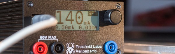
The calibration is performed in three steps – first with nothing connected to the Re:load Pro. Then a power supply set to approximately 9.99 volts is connected. The voltage displayed on the Re:load Pro is tweaked with the rotary encoder to display the same value as that of the power supply. My power supply has a rather cheap internal voltmeter, so I used a multimeter in parallel with the setup. With voltage done, the Re:load Pro will draw 2 amps from the power supply. You need to adjust the current displayed on the Re:load Pro such that it matches the voltage displayed on your power supply current meter. Again, since my supply doesn’t have the most accurate meter, I used a multimeter – this time in series with the Re:load and the power supply.

Taking Measurements

reload-pro-review-thumb
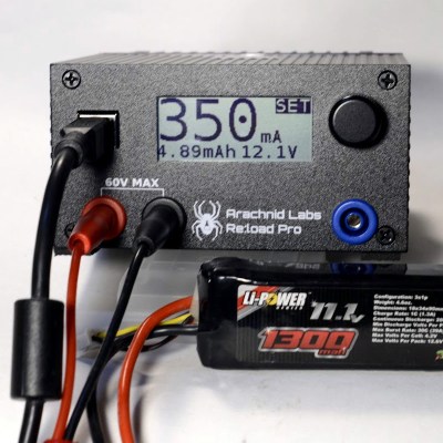
With all the preliminary work done, it’s time to make some measurements! Re:load pro has a simple user interface. everything is accessed with the rotary encoder on the front panel. Turn the dial to your desired value, and press to select. In my case, I wanted to check the voltage drop of a LiPo battery under various loads. I simply hooked up the battery and dialed 350ma on the encoder. The Re:load Pro showed me that the battery was holding at 12.1 volts, and a display on the lower left side showed me how many milli amp hours I had pulled from the battery.

The Re:load Pro’s USB connector isn’t just for power. It will show up on your PC as a serial device. Just open your favorite terminal emulator, set the port to 115200 baud 8/N/1, and you’re good to go. The Re:load Pro uses a simple text based command/response protocol, all the commands are outlined on the Arachnid labs page.

Conclusion:

Re:load Pro is one of the first of new breed of open source tools. Like the closed source Rigol Oscilloscope, it replaces tools which cost several times more. [Nick] and Arachnid Labs aren’t just resting on their success though – they’ve just finished up a kickstarter for their latest open source tool. Tsunami is an open source signal generator based upon the Arduino platform. Tools enable projects, and open source tools are the best way to push the entire ecosystem forward.


Editor’s Note: We are reviving the concept of “Reviews” on Hackaday. These were pioneered long long ago by Hackaday Alum [Ian Lesnet] with his post on smart tweezers but little has been done since. We see a lot of tools, parts, raw materials, and equipment flow through our inbox. We plan to post reviews as a new Hackaday Column. These reviews are not paid placement, they are chosen by editors and writers based on our own interest. This particular example is available in the Hackaday Store and we started with it because we already have the hardware in-hand. However, we will be reviewing items we do not sell and have already put out requests for review units. If you know of something you think worthy of a review, please let us know by submitting it to the tips line. Thanks!

-Mike Szczys, Managing Editor

Demoing An 8088

The demoscene usually revolves around the Commodore 64, and when you compare the C64 hardware to other computers of a similar vintage, it’s easy to see why. There’s a complete three-voice synthesizer on a chip, the hardware allows for sprites, a ton of video pages, and there are an astounding sixteen colors, most of which look good. You’re not going to find many demos for the Apple II, because the graphics and sound are terrible. You’re also not going to find many demos for an original IBM PC from 1981, because for thirty years, the graphics and audio have been terrible.

8088 MPH by [Hornet], [CRTC], and [DESire], the winner of the recent 2015 Revision Demo compo just turned conventional wisdom on its head. It ran on a 4.77 MHz 8088 CPU – the same found in the original IBM PC. Graphics were provided via composite output by a particular IBM CGA card, and sound was a PC speaker beeper, beeping sixty times a second. Here’s a capture of the video.

Because of the extreme nature of this demo, it is unable to run on any emulator. While the initial development happened on modern machines with DOSbox, finishing the demo needed to happen on an IBM 5160, equivalent to the 5150, but much easier to find.

Despite the meager hardware and a CPU that reads a single byte in four cycles, effectively making this a 1.19 MHz CPU, the team produced all the usual demoscene visuals. There are moire patterns, bobbing text, rotated and scaled bitmaps, and an astonishing 1024-color mode that’s an amazing abuse of 80×25 text mode with NTSC colorburst turned on.

Below you can find a video of the demo, and another video of the audience reaction at the Revision compo.

Continue reading “Demoing An 8088”