33C3: If You Can’t Trust Your Computer, Who Can You Trust?

It’s a sign of the times: the first day of the 33rd Chaos Communications Congress (33C3) included two talks related to assuring that your own computer wasn’t being turned against you. The two talks are respectively practical and idealistic, realizable today and a work that’s still in the idea stage.

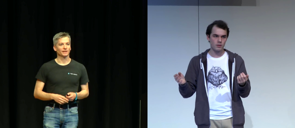
In the first talk, [Trammell Hudson] presented his Heads open-source firmware bootloader and minimal Linux for laptops and servers. The name is a gag: the Tails Linux distribution lets you operate without leaving any trace, while Heads lets you run a system that you can be reasonably sure is secure.

It uses coreboot, kexec, and QubesOS, cutting off BIOS-based hacking tools at the root. If you’re worried about sketchy BIOS rootkits, this is a solution. (And if you think that this is paranoia, you haven’t been following the news in the last few years, and probably need to watch this talk.) [Trammell]’s Heads distribution is a collection of the best tools currently available, and it’s something you can do now, although it’s not going to be easy.

Carrying out the ideas fleshed out in the second talk is even harder — in fact, impossible at the moment. But that’s not to say that it’s not a neat idea. [Jaseg] starts out with the premise that the CPU itself is not to be trusted. Again, this is sadly not so far-fetched these days. Non-open blobs of firmware abound, and if you’re really concerned with the privacy of your communications, you don’t want the CPU (or Intel’s management engine) to get its hands on your plaintext.

[Jaseg]’s solution is to interpose a device, probably made with a reasonably powerful FPGA and running open-source, inspectable code, between the CPU and the screen and keyboard. For critical text, like e-mail for example, the CPU will deal only in ciphertext. The FPGA, via graphics cues, will know which region of the screen is to be decrypted, and will send the plaintext out to the screen directly. Unless someone’s physically between the FPGA and your screen or keyboard, this should be unsniffable.

As with all early-stage ideas, the devil will be in the details here. It’s not yet worked out how to know when the keyboard needs to be encoded before passing the keystrokes on to the CPU, for instance. But the idea is very interesting, and places the trust boundary about as close to the user as possible, at input and output.

Making VR Controllers From The Ground Up

VR is going to be the next big thing in five to seven years, and with that comes the problem of what the controllers will look like. The Vive and PS Move are probably close to what the first successful consumer VR setup will look like, but there’s plenty of room for experimentation. [ShinyQuagsire] decided to experiment with VR, IMUs, and computer vision and managed to make a VR controller from the ground up.

The design of [Quagsire]’s VR controller is very similar to the PS Move controller: there’s a glowy ball on top of a Wii-nunchuckish controller. There’s a good reason for this design: a sphere projected onto a 2D surface is always a circle. By illuminating a sphere with an IR LED, [Quagsire] can get an OpenCV script to hone in on the controller.

One thing that was particularly hard for [Quagsire] was building the 3D printed controllers. The first hardware revision wasn’t designed for manufacturing on a 3D printer — there were curves everywhere and very few flat areas for bed adhesion. The second hardware revision corrected these problems, but there’s a world of difference between designing a 3D printable part and being able to calibrate and tune a 3D printer. In the end, [Quagsire] sent the files off to 3DHubs to put that whole ordeal behind him.

With the case printed, [Quagsire] filled it with IMU breakouts, buttons, and a tiny joystick. The brains of the controller is a Teensy 3.2 that has plenty of examples of how to transmit gyro data and button presses over serial. With that done, the only thing left to do was to tie everything together.

The controller worked, and [Quagsire] learned a lot in the process. Making VR controllers is hard, even though a lot of the project isn’t the optimal way of doing things. For the next iteration of this project, [Quagsire] might look at wireless, but for now the entire project is up on Github for everyone to take a look at.

The Story Of Kickstarting The OpenMV

Robots are the ‘it’ thing right now, computer vision is a hot topic, and microcontrollers have never been faster. These facts lead inexorably to the OpenMV, an embedded computer vision module that bills itself as the ‘Arduino of Machine Vision.’

The original OpenMV was an entry for the first Hackaday Prize, and since then the project has had a lot of success. There are tons of followers, plenty of users, and the project even had a successful Kickstarter. That last bit of info is fairly contentious — while the Kickstarter did meet the minimum funding level, there were a lot of problems bringing this very cool product to market. Issues with suppliers and community management were the biggest problems, but the team behind OpenMV eventually pulled it off.

At the 2016 Hackaday SuperConference, Kwabena Agyeman, one of the project leads for the OpenMV, told the story about bringing the OpenMV to market:

Continue reading “The Story Of Kickstarting The OpenMV”

Fail Of The Week: How I Killed The HiPot Tester

Have you ever wired up a piece of test equipment to a circuit or piece of equipment on your bench, only to have the dreaded magic smoke emerge when you apply power? [Steaky] did, and unfortunately for him the smoke was coming not from his circuit being tested but from a £2300 Clare H101 HiPot tester. His write-up details his search for the culprit, then looks at how the manufacturer might have protected the instrument.

[Steaky]’s employer uses the HiPot tester to check that adjacent circuits are adequately isolated from each other. A high voltage is put between the two circuits, and the leakage current between them is measured. A variety of tests are conducted on the same piece of equipment, and the task in hand was to produce a new version of a switch box with software control to swap between the different tests.

This particular instrument has a guard circuit, a pair of contacts that have to be closed before it will proceed. So the switch box incorporated a relay to close them, and wiring was made to connect to the guard socket. At first it was thought that the circuit might run at mains voltage, but when it was discovered to be only 5V the decision was made to use a 3.5mm jack on the switch box. Inadvertently this was left with its sleeve earthed, which had the effect of shorting out a DC to DC converter in the HiPot tester and releasing the smoke. Fortunately then the converter could be replaced and the machine brought back to life, but it left questions about the design of the internal circuit. What was in effect a logic level sense line was in fact connected to a low current power supply, and even the most rudimentary of protection circuitry could have saved the day.

We all stand warned to be vigilant for this kind of problem, and kudos to [Steaky] for both owning up to this particular fail and writing such a good analysis of it.

Our Fail Of The Week series has plenty to entertain the reader who is not of a nervous disposition. This isn’t the first fail to feature a suspect bit of connector wiring, not an unexpected short or even some magic smoke.

Parts Bin Bonanza Leads To Arduino FM Radio

Trolling eBay for parts can be bad for your wallet and your parts bin. Yes, it’s nice to be well stocked, but eventually you get to critical mass and things start to take on a life of their own.

This unconventional Arduino-based FM receiver is the result of one such inventory overflow, and even though it may take the long way around to listening to NPR, [Kevin Darrah]’s build has some great tips in it for other projects. Still in the mess-o-wires phase, the radio is centered around an ATmega328 talking to a TEA5767 FM radio module over I²C. Tuning is accomplished by a 10-turn vernier pot with an analog meter for frequency display. A 15-Watt amp drives a pair of speakers, but [Kevin] ran into some quality control issues with the amp and tuner modules that required a little extra soldering as a workaround. The longish video below offers a complete tutorial on the hardware and software and shows the radio in action.

We like the unconventional UI for this one, but a more traditional tuning method using the same guts is also possible, as this retro-radio refit shows.

Continue reading “Parts Bin Bonanza Leads To Arduino FM Radio”

How To Nail A Technical Presentation

Whether you’re an engineer, a maker, a hacker or a baker, at some point you’ll want to share your work with other people. Perhaps it’s a meeting at work to discuss process improvements, or a talk at a conference discussing some research you’ve done into hacking a new embedded platform. Or maybe you’ve developed a brand new cooking profile for rye breads that cuts energy usage in half. Whatever it is, there are techniques you can use to help you communicate effectively to a room full of people, and have fun doing it. Unlike some, I actually enjoy getting up in front of a crowd to present my work, so I’ve written this article to share with you some tips that can help you make a technical presentation that everyone will love — including you!

Editor’s Note: We planned the art for this article before the passing of Carrie Fisher. Leia certainly knew how to give a compelling technical presentation. We publish this in memory of a great actress.

Continue reading “How To Nail A Technical Presentation”

Pick-And-Place Machine For Candy

Every December and May the senior design projects from engineering schools start to roll in. Since the students aren’t yet encumbered with real-world detractors (like management) the projects are often exceptional, unique, and solve problems we never even thought we had. Such is the case with [Mark] and [Peter]’s senior design project: a pick and place machine that promises to solve all of life’s problems.

Of course we’ve seen pick-and-place machines before, but this one is different. Rather than identifying resistors and capacitors to set on a PCB, this machine is able to identify and sort candies. The robot — a version of the MeARM — has three degrees of freedom and a computer vision system to alert the arm as to what it’s picking up and where it should place it. A Raspberry Pi handles the computer vision and feeds data to a PIC32 which interfaces with the hardware.

One of the requirements for the senior design class was to keep the budget under $100, which they were able to accomplish using pre-built solutions wherever possible. Robot arms with dependable precision can’t even come close to that price restraint. But this project overcomes the lack of precision in the MeArm by using incremental correcting steps to reach proper alignment. This is covered in the video demo below.

Senior design classes are a great way to teach students how to integrate all of their knowledge into a final class, and the professors often include limits they might find in the real world (like the budget limit in this project). The requirement to thoroughly document the build process is also a lesson that more people could stand to learn. Senior design classes have attempted to solve a lot of life’s other problems, too; from autonomous vehicles to bartenders, there’s been a solution for almost every problem.

Continue reading “Pick-And-Place Machine For Candy”