In the days before integrated circuits became ubiquitous, providing advanced functionality in a single package, designers became adept at extracting the maximum use from discrete components. They’d use clever circuits in which a transistor or other active part would fulfill multiple roles at once, and often such circuits would need more than a little know-how to get working. It’s not often in 2024 that we encounter this style of circuit, but here’s [Maurycy] with a cheap microwave radar module doing just that.
One of the fun parts of the ESP32-S3 microcontroller is that it got upgraded to the newer Cadence Xtensa LX7 processor core, which turns out to have a range of SIMD instructions that can help to significantly speed up a range of tasks. [Shranav Palakurthi] recently used this to speed up the processing of video frames to detect corners using the FAST method. By moving some operations that benefit from SIMD over to an optimized version written in LX7 ASM, the algorithm’s throughput was increased by 220%, from 5.1 MP/s to 11.2 MP/s, albeit with some caveats.
The problem with the SIMD instructions in the LX7 other than them being very poorly documented – unless you sign an NDA with Cadence – is that it misses many instructions that would be really useful. For [Shranav] the lack of support for direct misaligned reads and comparing of unsigned 8-bit numbers were hurdles, but could be worked around, with the results available on GitHub.
Much of the groundwork for this SIMD implementation was laid by [Larry Bank], who reverse-engineered the SIMD instructions from available documentation and code samples, finding that the ESP32-S3 misses quite a few common SIMD instructions, including various shifts and unaligned reads and writes. Still, it’s good enough for quite a few tasks, as long as you can make it work with the available instructions.
[mircemk] shows how to create a simple non-contact proximity sensor using little more than an Arduino Nano board, and a convenient software library intended to measure the value of capacitors.
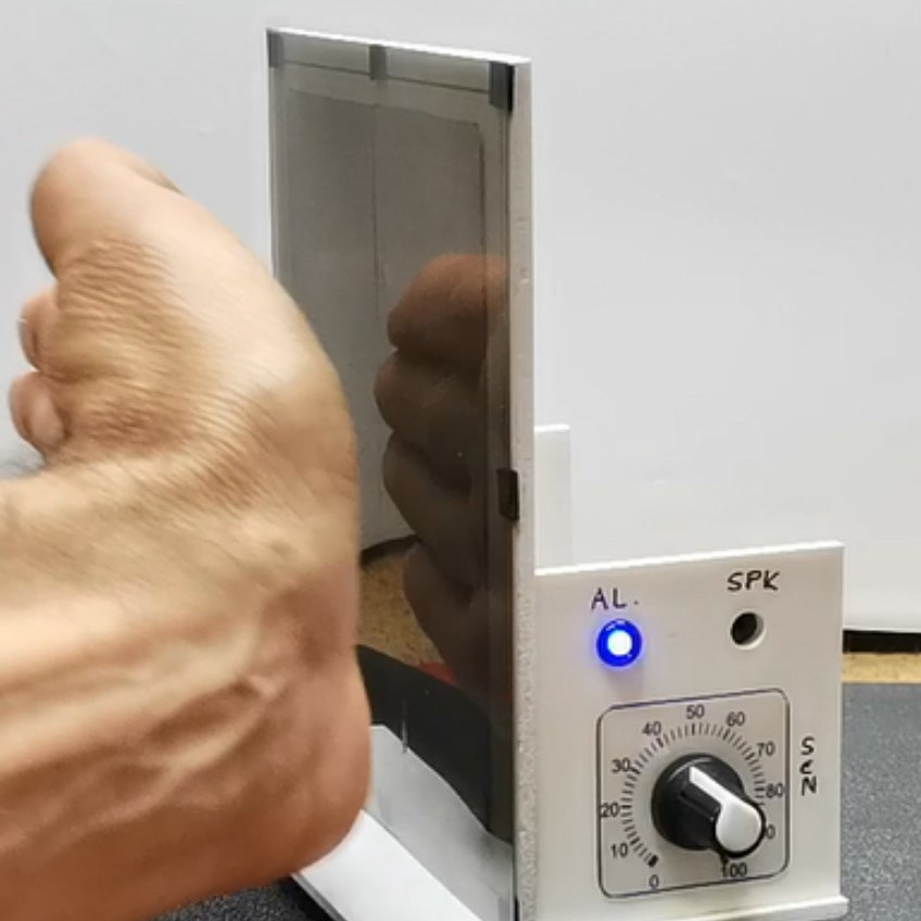
The prototype has a threshold set via potentiometer for convenience.
The basic idea is that it’s possible to measure a capacitor’s capacitance using two microcontroller pins and the right software, so by using a few materials to create an open-style capacitor, one can monitor it for changes and detect when anything approaches enough to alter its values past a given threshold, creating a proximity sensor.
The sensor shown here is essentially two plates mounted side-by-side, attached to an Arduino Nano using the Capacitor library which uses just two pins, one digital and one analog.
As configured, [mircemk]’s sensor measures roughly thirty picofarads, and that value decreases when approached by something with a dielectric constant that is different enough from the air surrounding the sensor. The sensor ignores wood and plastic, but an approaching hand is easily detected. The sensor also detects liquid water with similar ease, either in the form of pooled liquid, or filled bottles.
We’ve also seen a spring elegantly used as a hidden touch sensor that works through an enclosure’s wall by using similar principles, so the next time you need a proximity or touch-sensitive sensor in a project, reaching for the junk box might get you where you need to go. Watch [mircemk]’s sensor in action in the video, just below the page break.
There’s no shortage of USB-C chargers in all sorts of configurations, but sometimes, you simply need a few more charging ports on the go, and you got a single one. Well then, check out [bluepylons]’s USB-C splitter, which takes a single USB-C 5V/3A port and splits it into three 5V/1A plugs, wonderful for charging a good few devices on the go!
This adapter does things right – it actually checks that 3A is provided, with just a comparator, and uses that to switch power to the three outputs, correctly signalling to the consumer devices that they may consume about 1A from the plugs. This hack’s documentation is super considerate – you get detailed instructions on how to reproduce it, every nuance you might want to keep in mind, and even different case options depending on whether you want to pot the case or instead use a thermal pad for a specific component which might have to dissipate some heat during operation!
This hack has been documented with notable care for whoever might want to walk the journey of building one for themselves, so if you ever need a splitter, this one is a wonderful weekend project you are sure to complete. Wonder what kind of project would be a polar opposite, but in all the best ways? Why, this 2kW USB-PD PSU, most certainly.
The first part of the video below the break deals with the CAD steps necessary to produce the mould, and depending on your CAD proficiency may not be the most interesting part. The process creates a mould with two halves, a pouring hole, and registration points. Then a 3D printer produces it using flexible TPU. The pour is then simplicity itself, using a casting cement mix at a consistency similar to pancake batter. The video shows how a release spray provides easy separation, and the result is a fresh concrete owl and a mould ready for the next pour.
We can see that maybe readers have only so much space in their lives for concrete owls, but this process could be a valuable part of the armoury when it comes to making some less decorative items. It’s not the first time we’ve looked at this type of work.
Are you the kind of hacker who tries to pick up FreeCAD, but doesn’t want to go through a tutorial and instead pokes around the interface, trying to transfer the skills from a CAD suite you’ve been using before? I’ve been there too, and in my experience, FreeCAD doesn’t treat such forays lightly. It’s a huge package that enables everything from architecture to robotics design, so if you just want a 3D-printed case for a PCB project, the hill can be steep. So let’s take that first simple project as an example, and see if it helps you learn a little bit of FreeCAD.
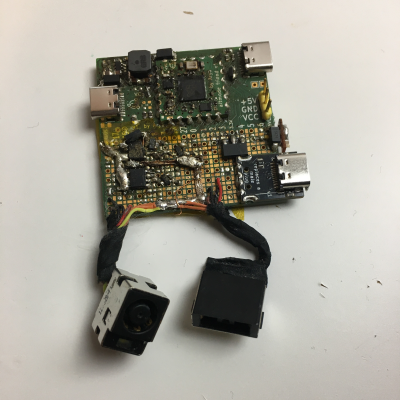
This board needs a case – badly.
As motivation, I recently built a USB-C PSU board that uses a DC PSU and does the USB-C handshaking to provide 20 V to a laptop. It is currently my only 100 W USB-C PSU, and my 60 W PSU just died, which is why I now use this board 24/7. I have brought it on two different conferences so far, which has highlighted a problem – it’s a board with tons of exposed contacts, which means that it isn’t perfectly travel-friendly, and neither it is airport-friendly – not that I won’t try and bring it anyway. So, currently, I have to watch that nothing shorts out – given the board has 3.3 V close to 20 V at 9 A, it’s a bit of a worry.
This means I have to design some sort of case for it. I was taught SolidWorks in the half a year that I spent in a university, and honestly, I’m tired of the licensing and proprietary format stuff. When it comes to more hobbyist-accepted tools like Fusion360, I just don’t feel like exchanging one proprietary software for another. So, FreeCAD is the obvious choice – apart from OpenSCAD, which I know and love, but I don’t always want to think up fifteen variable names for every silly little feature. That, and I also want to fillet corners every now and then.
For a full-open-source workflow, today’s PCB is designed with KiCad, too. Let’s see about installing FreeCAD, and the few things you need to import a KiCad board file into FreeCAD.
Electricity flow is generally invisible, silent, and not something that most humans want to touch, so understanding how charge moves around can be fairly unintuitive at first. There are plenty of analogies to help understand its behavior, such as imagining a circuit as a pipe of water, with pressure standing in for voltage and flow standing in for current. But you can flip this idea in reverse and use electric circuits to model other complex phenomena instead. [Oxx], for example, is using circuit theory to model his home’s heating systems.
To build his model, he’s using LTSpice, a free circuit simulation program. Using voltage to model temperature and current to model heat flow, he’s set up a model for his home to compare the behavior of a heat pump and a propane furnace. A switch model already in LTSpice with built-in hysteresis takes the place of the thermostat. Using temperature data for a single day in January [Oxx] can see how each of his two heating systems might behave, and the model for the heat pump is incredibly close to how the heat pump behaved in real life.
The model includes all kinds of data about the system, including the coefficient of performance of the heat pump and its backup electric resistive heater, and the model is fairly accurate at predicting behavior. Of course, it takes a good bit of work to set up the parameters for all of the components since our homes and heating systems won’t be included in LTSpice by default, but it does show how powerful an electric circuit analog can be when building models of other systems. If you’ve never used this program before, we’ve featured a few guides to getting started that you can take a look at.