2025 Pet Hacks Contest: Automatic Treat Dispenser Makes Kitty Work For It

Treat dispensers are old hat around here, but what if kitty doesn’t need the extra calories — and actually needs to drop some pounds? [MethodicalMaker] decided to link the treat dispenser to a cat wheel, and reward kitty for healthy behaviors. The dispenser can be programmed to make the cat run long enough to burn the calories of its treat. Over time, kitty can be trained to run longer between treats to really melt off the pounds.
The wheel itself is an off the shelf model called “One Fast Cat”; apparently these are quite cheap second hand as most cats don’t really see the point in exercise. [MethodicalMaker] glued evenly-spaced magnets along the rim in order to track the rotation with a hall effect sensor.  A microcontroller is watching said sensor, and is programmed to release the treats after counting off a set number of revolutions. Control over the running distance and manual treat extrusion is via web portal, but the networking code had difficulty on the Arduino R4 [MethodicalMaker] started with, so he switched to an ESP32 to get it working.

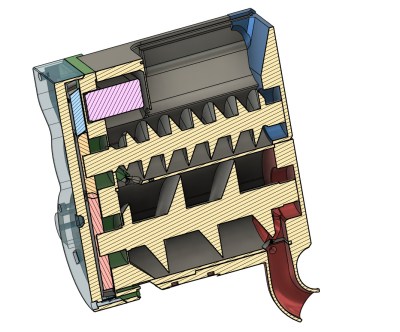
The real interesting part of this project is the physical design of the treat dispenser: it uses a double-auger setup to precisely control treat release. The first auger lives inside a hopper that holds a great many treats, but it tended to over-dispense so [MethodicalMaker] methodically made a second auger that sits beneath the hopper. The handful of treats extruded by the first auger are dispensed individually by the second auger, aided by a photosensor inside the exit chute to count treats. This also lets the machine signal when it needs refilling. For precise control, continuous servos are used to drive the augers. Aside from the electronics, everything is 3D printed; the STLs are on Printables, and the code is on GitHub.

If you don’t have a cat wheel, DIY is an option. If you don’t have a cat, we’ve also highlighted dog treat dispensers. If you don’t have either, check with your local animal shelter; we bet good money there are oodles ready to adopt in your town, and then you’ll have an excuse to enter one of your projects into our ongoing Pet Hacks Contest.

Continue reading “2025 Pet Hacks Contest: Automatic Treat Dispenser Makes Kitty Work For It”

Building A Motor Feed For The UE1 Vacuum Tube Computer’s Paper Tape Reader

Building a paper tape reader by itself isn’t super complicated: you need a source of light, some photoreceptors behind the tape to register the presence of holes and some way to pull the tape through the reader at a reasonable rate. This latter part can get somewhat tricky, as Usagi Electric‘s [David Lovett] discovered while adding this feature to his vacuum tube-era DIY reader. This follows on what now seems like a fairly simple aspect of the photosensors and building a way to position said photosensors near the paper tape.

As the feed rate of the paper tape is tied to the reading speed, and in the case of [David]’s also contains the clock for the custom tube-based UE1 computer, it determines many of the requirements. With 8 bits per line, the tape forms the ROM for the system, all of which has to be executed and used immediately when read, as there is no RAM to load instructions into. This also necessitates the need to run the tape as an endless loop, to enable ‘jumping’ between parts of this paper-based ROM by simple masking off parts of the code until the desired address is reached.

For the motor a slot car motor plus speed-reduction gear was chosen, with a design to hold these then designed in FreeCAD. Courtesy of his brother’s hobby machine shop and a CAD professional’s help, producing these parts was very easy, followed by final assembly. Guides were added for the tape, not unlike with a cassette player, which allowed the tape to be pulled through smoothly. Next up is wiring up the photodiodes, after which theoretically the UE1 can roar into action directly running programs off paper tape.

Continue reading “Building A Motor Feed For The UE1 Vacuum Tube Computer’s Paper Tape Reader”

Using An OLED Display’s Light For Embedded Sensors

These days displays are increasingly expected to be bidirectional devices, accepting not only touch inputs, but also to integrate fingerprint sensing and even somehow combine a camera with a display without punching a hole through said display. Used primarily on smartphone displays, these attempts have been met with varying degrees of success. But a paper published in the Communications Engineering journal describes a version which combines an OLED with photosensors in the same structure — a design that may provide a way to make such features much more effective.

The article by [Chul Kim] and colleagues of the Samsung Display Research Center in South Korea the construction of these bidirectional OLED displays is described, featuring the standard OLED pixels as well as an organic photodiode (OPD) placed side-by-side. Focusing on the OLED’s green light for its absorption characteristics with the human skin, the researchers were able to use the produced OLED/OPD hybrid display for fingerprint recognition, as well as a range of cardiovascular markers, including heart rate, blood pressure, etc.

The basic principle behind these measurements involves photoplethysmography, which is commonly used in commercially available pulse oximeters. Before these hybrid displays can make their way into commercial devices, there are still a few technical challenges to deal with, in particular electrical and optical leakage. The sample demonstrated appears to work well in this regard, but the proof is always in the transition from the lab to mass-production. We have to admit that it would be rather cool to have a display that can also handle touch, fingerprints and record PPG data without any special layers or sensor chips.

A dark brown bench suspended between two white and grey rectangular pillars. They are capped in the same brown HDPE material. Aluminum uprights go to a curved solar panel roof that looks somewhat similar to a paragliding chute. The bench is inside a clean-looking workshop with two large toolboxes against a plywood half wall.

Public Power, WiFi, And Shelter

In the US, we’re starting to see some pushback against hostile architecture, and in this vein, [benhobby] built a swanky public power and Wi-Fi access point.

This beautiful piece of infrastructure has 400 watts of solar plugged into 1.2 kWh of battery storage, and can dispense those electrons through any of its 120 VAC, USB-C, or USB-A plugs. The uprights are 3″ aluminum tubing attached to a base consisting of cinder blocks and HDPE panels. Power receptacles are housed in 3D printed enclosures with laser cut acrylic fronts. Three outdoor lights illuminate the stop at night, triggered by a photosensor.

The electronics and battery for the system, including the networking hardware, are in a weatherproof box on each side that can be quickly disconnected allowing field swaps of the hardware. Troubleshooting can then take place back at a workshop. One of the units has already been deployed and has been well-received. [benhobby] reports “There’s one in the wild right now, and it gets plenty of visitors but no permanent tenants.”

Want to see some more interesting hacks for public infrastructure? Check out this self-cooling bus stop, this bus bloom filter, or this public transit display.

Showing pulse oximeter and color sensor combining to measure oxygen in blood and skin tone

Perfecting The Pulse Oximeter

We’re always looking for interesting biohacks here on Hackaday, and this new research article describing a calibrated pulse oximeter for different skin tones really caught our attention.

Pulse oximeters are handy little instruments that measure your blood oxygen saturation using photoplethysmography (PPG) and are a topic we’re no strangers to here at Hackaday. Given PPG is an optical technique, it stands to reason that its accuracy could be significantly affected by skin tone and that has been a major topic of discussion recently in the medical field. Given the noted issues with pulse oximeter accuracy, these researchers endeavored to create a better pulse oximeter by quantifying skin pigmentation and using that data to offset errors in the pulse oximeter measurements. A slick idea, but we think their results leave a lot to be desired.

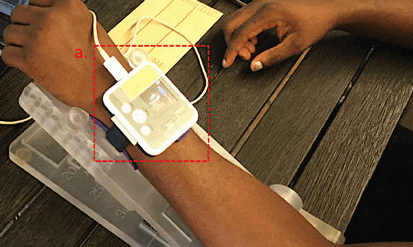
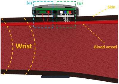
Diagram showing pulse oximeter and color sensor combining to measure oxygen in blood and skin toneTheir idea sounds pretty straightforward enough. They created their own hardware to measure blood oxygen saturation, a smartwatch that includes red and infrared (IR) light-emitting diodes (LED) to illuminate the tissue just below the surface of the skin, and a photosensor for measuring the amount of light that reflects off the skin. But in addition to the standard pulse oximeter hardware, they also include a TCS34725 color sensor to quantify the user’s skin tone.

So what’s the issue? Well, the researchers mentioned calibrating their color sensor to a standard commercially-available dermatology instrument just to make sure their skin pigmentation values match a gold standard, but we can’t find that data, making it a bit hard to evaluate how accurate their color sensor actually is. That’s pretty crucial to their entire premise. And ultimately, their corrected blood oxygen values don’t really seem terribly promising either. For one individual, they reduced their error from 5.44% to 0.82% which seems great! But for another user, their error actually increases from 0.99% to 6.41%. Not so great. Is the problem in their color sensor calibration? Could be.

We know from personal experience that pulse oximeters are hard, so we applaud their efforts in tackling a major problem. Maybe the Hackaday community could help them out?

Inside Digital Image Chips

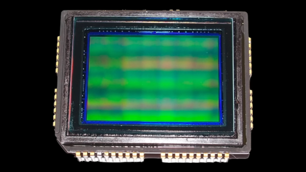
Have you ever thought how amazing it is that every bit of DRAM in your computer requires a teeny tiny capacitor? A 16 GB DRAM has 128 billion little capacitors, one for each bit. However, that’s not the only densely-packed IC you probably use daily. The other one is the image sensor in your camera, which is probably in your phone. The ICs have a tremendous number of tiny silicon photosensors, and [Asianometry] explains how they work in the video you can see below.

The story starts way back in the 1800s when Hertz noticed that light could knock electrons out of their normal orbits. He couldn’t explain exactly what was happening, especially since the light intensity didn’t correlate to the energy of the electrons, only the number of them. It took Einstein to figure out what was going on, and early devices that used the principle were photomultiplier tubes, which are extremely sensitive. However, they were bulky, and an array of even dozens of them would be gigantic.

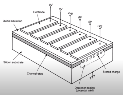
Semiconductor devices use silicon. Bell Labs was working on bubble memory, which was a way of creating memory that was never very popular. However, as a byproduct, the researchers realized that moving charges around for memory could also move around charges from photosensitive diodes. The key idea was that it was harder to connect many photodiodes than it was to create the photodiodes. Using the charge-coupled device or CCD method, the chip could manipulate the charges to reduce the number of connections to the chip.

CCDs opened up the digital image market, but it has some problems. The next stage was CMOS chips. They’d been around for a while since IBM produced the scanistor, but the sensitivity of these CMOS image chips was poor. Since most people were happy with CCD, there wasn’t as much research on CMOS. However, CMOS sensors would eventually become more capable, and the video explains how it works.

We’ve looked at image sensors before, too. The way you read them can make a big difference in your images.

Continue reading “Inside Digital Image Chips”

Flexible, Thin-Film Biosensors

We like to keep a pulse on the latest biosensor research going on around the world. One class of biosensors that have really caught our attention is the so-called thin-film sensors, pioneered by the Rogers Research Group at Northwestern University.

We’re no strangers to the flexible PCB here at Hackaday. Flexible PCBs have become increasingly accessible to small-scale developers and hobbyists, explaining why we’re seeing them incorporated into many academic research projects. The benefit of these types of sensors lies in the similarity of their mechanical properties to those of human skin. Human skin is flexible, so matching the flexibility of skin allows these thin-film sensors to adhere more comfortably and naturally to a person’s body. Continue reading “Flexible, Thin-Film Biosensors”