Cool WS2811 Trick Makes LED Art Installation Smooth

Normally, when a project calls for addressable LEDs, we just throw a strip of WS2812s and an Arduino together, cobble together some code from the examples in the FastLED library, and call it a day. We don’t put much thought into what’s going on under the hood, unless and until we run into an LED project that’s a little more challenging.

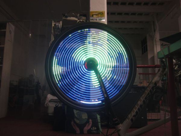
Inventor [Leo Fernekes] found himself in such a situation recently, when he pitched in on an LED art installation. The project called for rings of LED bars around the trunks of trees on a private estate. The physical size of the project and the aesthetic requirements created significant challenges, though. One of these was finding a way to control the LED bars, each of which draws about 100 mA and needs to be very smoothly dimmed. [Leo] looked at the WS2811 LED driver, but found that the low drive current and the 8-bit PWM output failed to tick either of those boxes.

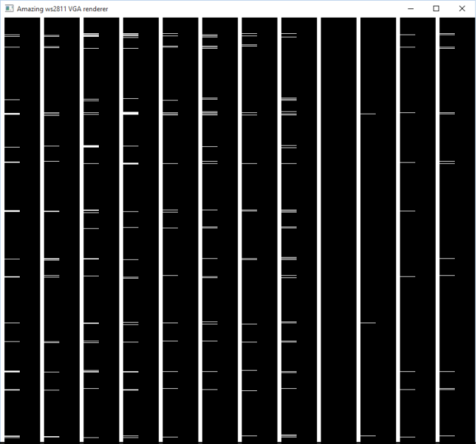
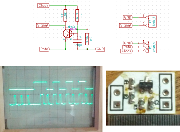
[Leo] solved both problems by using two of the three PWM channels on the chip in concert — one to control the current and one to PWM the LED. The circuit he came up with is deceptively simple — just four transistors, a Schottky diode, and a bunch of passives. The other clever bit is the data interface between LED bars, which can be configured as either single-ended or differential. This allows the same interface to be used for the short distance between bars on a tree, and the longer runs between trees.

As usual, [Leo] does a great job of explaining his design and how it works, which we find very instructional. He did something similar when he managed to dim a non-dimmable LED fixture.

Continue reading “Cool WS2811 Trick Makes LED Art Installation Smooth”

Using WS2811 Chip To Drive Incandescent Lamps

What makes the WS2812-style individually addressable pixel LEDs so inviting? Their rich colors? Nope, you can get RGB LEDs anywhere. Their form factor? Nope. Even surface-mount RGBs are plentiful and cheap. The answer: it’s the integrated controller. It’s just so handy to speak an SPI-like protocol to your LEDs — it separates the power supply from the data, and you can chain them to your heart’s desire. Combine this controller and the LEDs together in a single package and you’ve got a runaway product success.

But before the WS2812, there was the WS2811 — a standalone RGB controller IC. With the WS2812s on the market, nobody wants the lowly WS2811’s anymore. Nobody except [Michael Krumpus], that is. You see, he likes the old-school glow of incandescent, but likes the way the WS2812 strings are easy to drive and extend. So he bought a bag of WS2811s and put the two together.

The controller IC can’t handle the current that an incandescent bulb requires, so he added a MOSFET to do the heavy lifting. After linking a few of these units together, he discovered (as one does with the LED-based WS2812s eventually) that the switching transients can pull down the power lines, so there is a beefy capacitor accompanying each bulb.

He wanted each bulb to be independently addressable, so he only used the blue line of the RGB controller, which leaves two outputs empty. I’m sure you can figure out something to do with them.

Needless to say, we’ve seen a lot of WS2812 hacks here. It’s hard to pick a favorite. [Mike] of “mike’s electric stuff” fame built what may be the largest installation we’ve seen, and this hack that effectively projection-maps onto a randomly placed string of WS2812s is pretty cool. But honestly, no project that blinks or glows can go far wrong, right?

Continue reading “Using WS2811 Chip To Drive Incandescent Lamps”

Driving WS2811 LEDs With…VGA?

We thought we’d seen it all. All the ways to drive WS2811/2812 “Neopixel” LEDs, that is. And then [Steve Hardy] comes up with a new one: hacking a computer’s VGA output to drive 500 WS2811s in a string. And it’s quite a hack. You can check out the video (it’s worth enduring the horrible wind noise) below the break.

bits[Steve]’s big realization was that he could send the digital data that the Neopixels needed by carefully selecting a resolution and clock rate for the VGA to match the timings that the WS2811 modules wanted. A resolution of 840×1000 at 28MHz produces 70 pixels per WS2811 bit, or 12 bits per line. This means two VGA lines need to be sent for the RGB triple for each LED, hence the 1000 rows.

There are some further tricks before [Steve] got around to writing a custom OpenGL shader that converts regular graphics to his strange black-and-white bit pattern to drive the LEDs, but you’re going to have to read [Steve’s] blog for all that. If you’re waiting for a full code write-up, [Steve] says that one’s pending.

We’re just stoked to see the computing power that lies within a video card used for other purposes. Once you think of the VGA output as a general-purpose high speed (analog!) output, it opens up a whole bunch of possibilities if you can write the corresponding video software. As [Steve] points out, he’s only using the red channel right now — he could trivially add another 1000 LEDs just by tweaking his video code.

Continue reading “Driving WS2811 LEDs With…VGA?”

Bike Persistance of Vision

Simple POV Bike Effects With WS2811 Strips

[Andrew] wrote in with a new take on the classic persistence of vision bike spoke hack. While many of these POV setups use custom PCBs and discrete LEDs, [Andrew]’s design uses readily available off-the-shelf components: WS2811 LED strips, an Arduino, an Invensense IMU breakout board, and some small LiPo batteries.

[Andrew] also implemented a clever method of controlling his lights. His code detects when the rider taps the brakes in certain patterns, which allows changing between different light patterns. He does note that this method isn’t incredibly reliable due to some issues with his IMU, so now he senses when the rider taps on the handlebars as well.

If you want to build your own bike POV setup, you’re in luck. [Andrew] wrote up detailed instructions that outline the entire build process. He also provides links to sources for each part to make building your own setup even easier. His design is pretty affordable too, coming in at just under $50 per wheel. Check out a video of [Andrew]’s setup in action after the break.

Continue reading “Simple POV Bike Effects With WS2811 Strips”

Fail Of The Week: WS2811 Pixel Failure On FLED

This Fail of the Week project comes from one of Hackaday’s own. [Ben] took on the FLED data visualization project as a way to make the SupplyFrame decor a lot more fun. He had quite a bit of help soldering the 96 WS2811 pixels into their custom made 6’x4′ enclosure and the results are really awesome. In addition to showing server load and playing games, FLED has become something of a job interview. Sit the prospective employee down at a terminal and give them an hour to code the most interesting visualization they are capable of.

But two weeks ago [Ben] staggered into the office and found the display was dead. Did he try turning it off and back on again? Yes, but to no avail. The power supply wasn’t the issue and there was no option but to pull the display off the wall and crack it open for a look at all those pixels. Since every one of them had 4 solder joints on either side he figured the problem was with a broken connection. But not so. He resorted to a binary search for the offending pixel by  cutting the strand in half, and testing each portion. He tracked it down to the pixel whose underside was blackened as you can see above.

[Ben] thinks one of the capacitors inside the sealed enclosure blew, but isn’t certain. Feel free to tell us what you think failed in this component. But the thing we’d really like to know is if there is a more clever way to sniff out the offensive pixel without cutting the connections? Four hours on the floor with this thing (and no knee-pads) and [Ben] has sworn off sourcing pixels from random Chinese suppliers. He might go with pre-assembled strings next time. We chuckle; this is the high-tech equivalent of trying to get old strands of Christmas lights to work.

If you haven’t seen FLED in action, check it out after the break. It amazing how LED intensity and quality diffuser material can make a perfect grid of LEDs seem to dance in waves and color curves.

Continue reading “Fail Of The Week: WS2811 Pixel Failure On FLED”

WS2811 SPI Driver Using One Transistor And Passives

ws2811-spi-driver

We love the WS28xx projects because even if we never plan to use them, the signal timing is like the most addictive puzzle game ever. For instance, check out this WS2811A driver which uses hardware SPI to generate the signals.

The WS28xx offerings place a microcontroller inside an RGB LED, allowing them to be individually addressed in very long chains or large matrices (still a chain but different layout). But the timing scheme used to address them doesn’t play well with traditionally available microcontroller peripherals. [Brett] had been intrigued by some of the attempts to bend hardware SPI to the will of the WS2811 — notably [Cunning_Fellow’s] work featured in this post. He took it a great step forward by simplifying the driver to just one transistor, three resistors, and a capacitor.

Click through the link above for his step-by-step description of how the circuit works (it’s not worth re-explaining here as he does a very concise job himself). The oscilloscope above shows the SPI signal on top and the resulting timing signal below. You will notice the edges aren’t very clean, which requires the first pixel to be very close to the driver or risk further degradation. But, since the WS28xx drivers feature a repeater which cleans up signals like this, it’s smooth sailing after the first pixel.


WS2811 Can Be Addressed At 800kHz Using A 8MHz Clock

ws2811-running-at-8mhz

Timing is everything and that’s why most communication protocols require a very accurate clock source. The WS2811 LED strip controllers are no different. But [Danny] figured out a way to drive them reliably with an 8MHz clock source.

The WS2811 has become one of the most popular controllers for RGB pixels and strips alike. We’ve seen several hacks used to address them, including the 16MHz AVR technique that inspired [Danny] to take on this project. He planned to use that library but the 25-day shipping time for a 16MHz crystal drove home to invent a way to use the internal oscillator instead.

The gist of the hack is that he wrote assembly code to handle pairs of binary bit values. With a code block for each of the four possible combinations in hand he had to find a way to craft the conditional jumps to preserve accurate timing. After hitting the wall trying to solve this puzzle by hand he wrote a C++ program to solve it for home. The proof is in this video which shows one chip driving multiple Larson scanners on a single strip.

Continue reading “WS2811 Can Be Addressed At 800kHz Using A 8MHz Clock”